
 Your location:Home → Pump valve fittings → Pump products → Oil pump → SYB-A manual dual speed single outlet oil pump
 |
Product name: | SYB-A manual dual speed single outlet oil pump | |||||
| specification: |   Zoom in on the image Zoom in on the image |
||||||
| Category: | Pump valve fittings -- Oil pump | ||||||
| |
Price: | factory price | |||||
| Brand: | Shanghai | ||||||
| Place of Origin: | China | ||||||
| |
Available Quantity: | batch | |||||
| delivery cycle: | Spot goods (or inquire by telephone) | ||||||
 |
|
||||||
Introduction
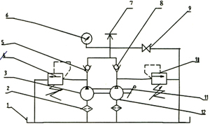
SYB-A manual oil pump is a small hydraulic pump station that converts manual mechanical energy into liquid pressure energy. Installing a pedal and spring reset mechanism can be changed to foot operated.
With the matching oil cylinder and specialized tools, various operations can be carried out, such as lifting, bending, straightening, shearing, riveting, assembly, disassembly, and some construction and military construction.
The main characteristics of an oil pump are: manual power, high pressure, ultra small size, easy to carry, simple operation, and wide application range.
Technical parameters
|
Model number |
work pressure MPa |
Maximum displacement Ml/time |
Maximum shaking force N |
Fuel tank capacity L |
Export Snail Stripe metric system |
Overall dimensions Length × Width × Height |
Weight Kg | ||
|
High pressure |
low pressure |
High pressure |
low pressure | ||||||
|
SYB-A |
sixty-three |
one |
two point three |
twelve point five |
five hundred |
zero point seven |
M16X1.5 |
600X100X150 |
nine |
|
SYB-A/0.7 |
sixty-three |
one point five |
two point three |
fourteen point five |
five hundred |
zero point seven |
M14X1.5 |
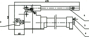
635X110X140 |
eight |
|
SYB-A/3 |
sixty-three |
one point five |
two point three |
fourteen point five |
five hundred |
three |
M14X1.5 |
350X160X140 |
ten |

|
Phenomenon of malfunction |
Main reasons |
Elimination Method |
| 1. Insufficient or no pressure. When the pressure rod is shaken, the oil cylinder does not work or cannot output the rated pressure. | 1. The pressure adjustment of the high-pressure valve is too low |
Check the pressure of the hydraulic system with a pressure gauge. If the pressure is below 63MPa, tighten the pressure valve screw to reach the specified value. |
| 2. High pressure valve spring damaged or losing elasticity | Replace the high-pressure valve spring | |
| 3. Is the high-pressure valve slightly worn? | The method of repairing the political valve mouth: lightly tap the first level precision steel ball 1-2 times with your hand. If it is severely worn, you can use a drill bit to re drill it flat. If it is even more severe, the pump body will be scrapped. | |
| 4. Is there slight wear on the valve mouth of the unloading valve? | The method of repairing the political valve mouth: lightly tap the first level precision steel ball 1-2 times with your hand. If it is severely worn, you can use a drill bit to re drill it flat. If it is even more severe, the pump body will be scrapped. | |
| 5. Wear of oil pump column plug hole | Replace the plunger and correct the plunger hole. | |
| 2. The oil pump experiences a sudden decrease in oil delivery and pressure during use. | 1. The high-pressure spring undergoes permanent deformation or is broken | Replace the high-pressure valve spring |
| 2. The low-pressure valve spring undergoes permanent deformation or is broken | Replace the low-pressure valve spring | |
| 3. Impurities in the low-pressure valve have damaged the sealing of the check valve, one-way valve, and low-pressure valve | Disassemble the oil pump, clean it with gasoline or light oil, reassemble and inject clean oil | |
| 3. The oil pump's fuel delivery rate decreases, and there is insufficient or no pressure at low pressure. | 1. The low-pressure valve spring is damaged or has lost its elasticity | Replace the low-pressure valve spring |
| 2. The low-pressure valve has slight wear and tear | Correct the valve mouth | |
| 4. The oil pump supply is interrupted and produces weak noise. | 1. Low oil level, absorbing air | Fill the oil and increase the oil level |
| 2. Inlet blockage | Remove impurities from the suction port | |
| 3. The vent valve is closed, and the air pressure inside the oil storage pipe decreases | Open the vent valve | |
| 5. The plunger and pressure rod automatically rebound. | 1. The valve mouth of the one-way valve has slight wear and tear | Correct the valve mouth |
| 2. The one-way valve spring loses its elasticity or is damaged | Replace the one-way valve spring | |
| 3. Particle impurities at the valve mouth of the one-way valve | Clean the one-way valve area | |
| 6. When using static pressure, there is a slow decrease in pressure. | Failure of each sealing point | Check all seals, tighten screws or replace rubber rings |
| 7. There is a phenomenon of compressed air. | Insufficient exhaust | Pump the abdomen upwards several times to eliminate it |

 Related Products:
 AOB-25 series oil pump motor XQD-0.75-3 DC Forklift (Oil Pump) Motor XYQDB-13H Explosion proof AC variable frequen.. NZ1.0SK Concentrated oil CNC automatic lubric.. NZ Dual display thick oil CNC automatic lubri.. XY Dual Display Thin Oil CNC Automatic Lubric.. XC4.0SK Thin oil CNC automatic lubrication oi.. Y-YNC Oil pump plug-in motor Y-B series oil pump dedicated asynchronous mo.. HGP series gear oil pump Related articles:
 Pump products
  pump head air pump electric pump Process pump vane pump frequency conversion pump variable displacement pump manual pump pressure pump plastic pump gear pump Mid open pump mixed-flow pump centrifugal pump feed pump circulation pump Drainage pump rotary pump pipeline pump submersible pump axial flow pump magnetic drive pump self-priming pump fire pump vortex pump multistage pump vacuum pump chemical pump screw pump submerged pump metering pump diaphragm pump reciprocating pump plunger pump drive pump canned motor pump pressure test pump marine pump air conditioning pump civilian pump Sanitary pump Insulated pump peristaltic pump lubrication pump cooling pump jet pump fountain pump Asphalt pump Aeration machine Slag(mud)slurry pump Sewage pump Oil pump
  valve products actuator pipe fittings sealing element fan
 Home|Quality Commitment|Ordering|Payment method|product delivery|support|Disclaimer|Contact Us
Copyright®2011 www.91way.com Copyright.
Phone:+86-21-66770508 +86-13916500500 Fax:+86-21-66108310
Email:91way@163.com Wechat:40606422
沪ICP备2021005791号  沪公网安备31010702003255号

