1、 Overview:
The WP-120-4 dual tachometer is a new generation intelligent speedometer that uses a novel single-chip microprocessor as the main chip. This product can be paired with two magnetic electric speed sensors to measure two speeds, with three relay alarm outputs and an RS485 communication interface; Mainly used for two speed monitoring points of mechanical equipment.
The following will introduce the performance and operation of the display device in order to effectively and reasonably use it.
2、 Main technical performance of WP-120-4 dual tachometer:
1. Power supply: 85-285V, 50/60Hz
2. Input frequency: 1.0Hz to 10000Hz,
3. Input signal: matched with magneto electric speed sensor
4. Speed measurement range: Dual channel 30~9999 (decimal point can be set arbitrarily)
5. Measurement accuracy: ± 0.05% (digital display)
6. Coefficient setting: 1.0 (user can set)
8. Sampling time: 0.1-5.0 seconds (factory set to 1.0 seconds)
9. Operating environment: Temperature range of 0-50 ℃
Relative humidity ≤ 85%
10. Hole size: 92 × 92
11. Dimensions: 96 × 96 × 110
12. Weight: less than 1.0kg
3、 Operating instructions:
Before formal use, power on the display device and it will display "8888." and "8888.". If there is no signal for 5 seconds, it should display "0" and "0"; Under normal measurement conditions, "XXXX." and "XXXX." are displayed, indicating the rotational speeds of channel 1 and channel 2, respectively.
2. Parameter setting:
a. The "Settings" button is a parameter setting gear shift button. Press the "Settings" button to enter the setting state, and display A, B, C, D, E, G, H, I, J in sequence.
b. The "◄" key is the left shift key. Press the "◄" button in order to flash and display decimal points in units, tens, hundreds, thousands, and tens of thousands.
c. ▲ "is the plus 1 key. Press the "▲" button to increase the flashing position by 1; When the decimal point is displayed, press the "▲" key to move the decimal point to the left; When the E mode is displayed and a decimal point appears, press the "▲" key to confirm and save the set parameters, and exit the setting state at the same time.
d. This instrument has ten parameters: A, B, C, D, E, F, G, H, I, and J. A represents the coefficient (set to "1.0" at the factory); B represents the zero adjustment value of analog output 1 (not defined locally); C represents the linear parameter of analog output 1 (not defined locally); D represents the full range of analog output (not defined locally); The E parameter represents the communication address; F represents the sampling time, which can be adjusted between 0.1 and 5.0 (factory set to 0.5S); G represents the pre alarm value, H represents the overspeed alarm value; I represents the zero adjustment value of analog output 2 (not defined locally); J represents the linear parameter of analog output 2 (not defined locally), and the decimal point of J parameter represents the baud rate of communication.
**J parameter decimal point selection baud rate:
xxxx. : 4800bps
xxx.x : 9600bps
xx.xx : 28800bps
x.xxx : 57600bps
The combination of the setting key, ◄ key, and ▲ key can change the value of any parameter. To save the changed parameter for a long time, it must be switched to the E parameter state. When the decimal point of the E parameter appears, press and hold the ▲ key for 2 seconds, and the parameter will be rewritten and saved. After pressing the reset button, the WP-2 tachometer returns to its working state.
e. The combination of the "Set", "◄", and "▲" keys can set each parameter bit by bit, and the decimal point can be moved to achieve any number setting within 0.0001 to 99999.
f. Press the 'reset' button, and the machine will be in the initial startup state.
3. Parameter calculation method:
This instrument converts the rotational speed into pulse frequency through corresponding sensors and then measures it. The final step is to measure the frequency and multiply it by an appropriate coefficient to enable the instrument to directly read the physical quantity.
Calculation formula: 60 × D/R=A × P
A represents the set coefficient
P represents the number of pulses per revolution of the sensor
D/R represents the ratio of direct reading physical quantity to rotational speed
The following example illustrates the method of exporting coefficient A:
(1) Assuming D/R=1, which means the speed ratio is 1 and the display is also the speed (r/min), and assuming the number of pulses P is 2, then:
A = 60×D/R×(1/P) = 30
The coefficient derived from this is 30, which can be set to 30.0 when setting.
4. Provide examples to illustrate the settings of coefficients and parameters.
Set coefficient A to 12.345 and parameter C to xxx.xx.
Press the "Settings" button. When A appears, press the "◄" button. When the position flashes, press the "▲" button to increase the position to 5; Press the "◄" key again, and when the ten digits flash, press the "▲" key to increase to 4; Press the "◄" key again, and when the hundred digits flash, press the "▲" key to increase the digit to 3; Press the "◄" key again, and when the thousand digit is flashing, press the "▲" key to increase the digit to 2; Press the "◄" key again, and when the ten thousand digits flash, press the "▲" key to increase the value to 1. Press the "◄" key, and when the decimal point appears, press the "▲" key to move the decimal point to the left, making A 12.345.
Press the "Settings" button, and when B appears, the setting method is the same as A;
Press the "Settings" button, and when C appears, the setting method is the same as A.
Press the "Settings" button, and when D appears, the setting method is the same as A;
Press the "Settings" button. When E appears, press the "◄" button until a decimal point appears, then press the "▲" button to confirm and save the set parameters, and exit the setting state. Other parameters will not be elaborated.
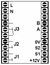
5. Wiring method:
+12V, 0V: Provide power for sensors that require power supply;
S1 and 0V: Connect the two output terminals of magneto electric sensor 1 respectively;
S2 and 0V: Connect the two output terminals of magneto electric sensor 2 respectively;
L. N: The working power supply for the instrument is AC 85-285V, 50/60Hz.
J1 relay 1, corresponding to the pre alarm of channel 1, normally starting; When the speed of channel 1 is greater than or equal to the pre alarm value G, relay 1 will activate.
J2 relay 2, corresponding to the pre alarm of channel 2, normally starting; When the speed of channel 2 is greater than or equal to the pre alarm value G, relay 2 will activate.
J3 relay 3, corresponding to overspeed alarm, normally open/closed end; When the speed of any channel is greater than or equal to the overspeed alarm value H, relay 3 will activate.
A communication terminal, (RS485 T/R+)
B communication end, (RS485 T/R-)


 Your location:Home → instrumentation and meters → tachometer → tachometer → WP-120-4 Dual tachometer

 Zoom in on the image

 Related Products:
 140ZCF-B10,140ZCF-B10D type permanent magnet ..
 Electrical instruments
  tachometer
 沪公网安备31010702003255号
