The LGZK series intelligent flow measurement and control instrument, commonly known as the self-control electronic water meter (hereinafter referred to as the measurement and control instrument), is a high-tech new product developed by our company based on the actual situation of high-pressure water injection in oil fields in China. It combines and absorbs international advanced technology, and relies on our company's strong foundation of long-term production of electronic water meters, high-precision flow meters and other series products. Through technology grafting, it has been carefully developed with precise flow measurement, intelligent data processing, instant flow arbitrary setting and automatic adjustment functions.
The successful development of this new product has completely changed the traditional practice of manually adjusting the water injection flow rate. Traditional manual flow regulation is not only labor-intensive and time-consuming, but also prone to human errors or inaccurate data. Especially at night, the unattended water distribution rooms in oil fields can experience severe loss of control over water injection flow due to large fluctuations in water injection pressure, resulting in low water injection efficiency and directly affecting the recovery rate. By using this measuring and controlling instrument, its excellent product performance can truly meet the process requirements of evenly injecting water according to the injection volume. It can be said that this is a major technological innovation in the field of oilfield water injection, which will bring significant economic and social benefits.
This series of measuring and control instruments comes in two types: integrated and split. There are multiple specifications of flow measurement ranges for the same caliber, and the external power supply is divided into AC and DC types, which can meet the needs of users to order and select according to the situation of different blocks as much as possible; The shell structure adopts a detachable design with a "removable core" to facilitate user maintenance and periodic calibration; The application of a series of advanced electronic and electrical technologies, such as overload and overheating protection, earthquake resistance, and anti-interference of motors, makes products more perfect and durable.
2. Main functions and features
Display total flow, instantaneous flow, date, and daily flow;
Arbitrary setting and automatic regulation of instantaneous flow rate;
Store daily traffic data for 2 years;
Signal output (pulse signal, current signal, RS-485 communication interface)
Flow cut-off, regulation, and opening indication (opening and closing valves);
The combination of built-in power supply and external power supply ensures that the flow measurement function operates normally when the external power supply is lost;
Detachable structure, convenient for maintenance and weekly inspection;
The instrument indication error is corrected by segmented linear interpolation, with high correction accuracy.
3. Purpose:
Measurement and control instruments are mainly used for measuring the volumetric flow rate, setting and automatically adjusting the instantaneous flow rate, and cutting off the flow rate in engineering pressure pipelines such as high-pressure water injection, polymer injection, water mixing, and dilute oil mixing in oil fields. They can also be used for measuring and controlling the liquid flow rate in other industrial pipelines.
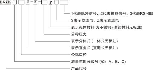
4. Model designation and meaning

5. Main technical indicators
a) Nominal caliber: 25-50mm;
b) Nominal pressure: 10-32MPa;
c) Environmental temperature: -30~80 ℃;
d) Relative humidity of the environment: ≤ 85%;
e) Atmospheric pressure: 86-106kPa;
f) Applicable media: water, oily wastewater, and light oil;
g) Medium temperature: 0-90 ℃;
h) Pressure loss: < 0.2MPa
i) Protection level: IP 65;
j) Power supply: (optional) (1) single-phase AC220 ± 20V 50Hz; (2) DC24V.
k) Measurement accuracy level (optional): 1.0, 1.5, 2.0;
l) Fully open close valve operation time: 30s;
m) Motor power: 50-120W;
n) Flow measurement range and control accuracy (see Table 1).
|
Nominal diameter mm |
twenty-five
|
forty
|
fifty
|
|
Flow range classification number |
A |
B |
C |
A |
B |
A |
B |
C |
|
Upper limit flow rate m3/h |
twelve |
five |
three |
twenty |
twelve |
thirty |
twenty |
twelve |
|
Lower limit flow rate m3/h |
zero point four eight |
zero point two |
zero point one two |
zero point eight |
zero point four eight |
one point two |
zero point eight |
zero point four eight |
|
Instantaneous flow control accuracy (dead zone) m3/h |
±0.1
|
±0.1
|
|
Pulse signal output flow coefficient n/m 3 |
ten thousand |

 Your location:Home → instrumentation and meters → flow meter → flow controller → LGZK series intelligent flow measurement and control instrument

 Zoom in on the image

 Related Products:
 Electrical instruments
  current meter
 沪公网安备31010702003255号
