
| Product name: | OESU-JH8 electronic mutual inductance collector | ||||||
| specification: |  |
||||||
| Category: | High voltage electrical appliances -- electronic instrument transformer | ||||||
| Price: | factory price | ||||||
| Brand: | Shanghai | ||||||
| Place of Origin: | China | ||||||
| Available Quantity: | batch | ||||||
| delivery cycle: | Spot goods (or inquire by telephone) | ||||||
|
|||||||
1、 Overview (Description)
The collector of electronic transformers can collect protection current signals through Rogowski coils, measure current signals through LPC low-power coils, and collect voltage signals through capacitive dividers. The energy harvesting coil or laser provides power for the collector, while also taking into account AC and DC sampling.
3、 Structure Introduction (Construction)
The collector of the photoelectric transformer is used to sample the analog input, perform analog-to-digital conversion, and transmit the data to the combiner through optical fiber.
The energy and data are transmitted between the collector and the combiner through only two optical fibers.
The collector provides three analog inputs, namely voltage, protection current, and measurement current, which enter the analog-to-digital conversion circuit through low-pass filtering. The analog-to-digital conversion circuit adopts a high-precision, high sampling rate 16 bit AD converter, and its signal-to-noise ratio can reach 90 decibels.
The collector adopts an ultra-low power 16 bit RISC system CPU, ensuring good performance with low power consumption.
The power circuit is responsible for providing power to various parts of the collector and extracting sampling interrupts. In the sampling interrupt, the CPU starts data sampling and conversion, and packages the converted data. The packaged data is modulated and sent to the combiner through optical fiber.
The main working power supply of the collector comes from the laser power supply. The energy obtained from the energy harvesting coil is rectified and filtered, and used as a thermal backup power source for the collector's operation.
4、 Outline and installation dimension diagram of OESU-JH8 electronic mutual inductance collector
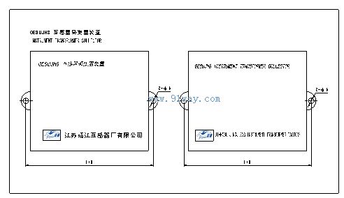
OESU-JH8 electronic mutual inductance collector

Home|Quality Commitment|Ordering|Payment method|product delivery|support|Disclaimer|Contact Us
Copyright®2011 www.91way.com Copyright.
Phone:+86-21-66770508 +86-13916500500 Fax:+86-21-66108310
Email:91way@163.com Wechat:40606422
沪ICP备2021005791号 ![]() 沪公网安备31010702003255号
沪公网安备31010702003255号