Overview
In general, devices that generate pressure are driven by electric motors, such as air compressors, water pumps, etc. The operation and stop of the electric motor will directly affect the presence and magnitude of the pressure. To keep the pressure within a certain range, it is impossible to control the operation of the motor manually. In this case, GYD series pneumatic automatic control switches are used, which not only achieve operational automation, but also save manpower, energy, and extend the service life of the machine.
This type of switch is not only suitable for automatic control of air pressure, but also for controlling water pressure. After adding some accessories, the two can also be used as automatic boiler alarms, pressure relief, and automatic water addition. Therefore, switches can be widely used in situations where air pressure is automatically controlled.
Structural characteristics of GYD series pressure switch
The switch is mainly composed of a plastic shell, an intake connector, an exhaust connector, a pressure regulator, and electrical contact components.
working principle
After the motor starts running, the pressure generated directly enters the switch. Under the action of the sensing diaphragm, the thrust generated interacts with the pressure spring to move the transmission plate upward and drive the springboard, causing the jump spring to pass through the dead point. Under the action of elastic force, it quickly disengages the moving contact and fixed contact of the electrical contact part, cuts off the power supply, and the motor stops running.
At this point, the pressure reaches the set value (upper limit). As it is used, the pressure begins to decrease. When the pressure drops to the pressure difference (lower limit), the transmission plate moves downward under the action of the pressure spring and drives the jump spring to quickly close the moving contact after passing through the dead point. When the power is turned on, the motor automatically starts and runs, and the pressure rises again, thus achieving automatic air pressure control through repeated operation.
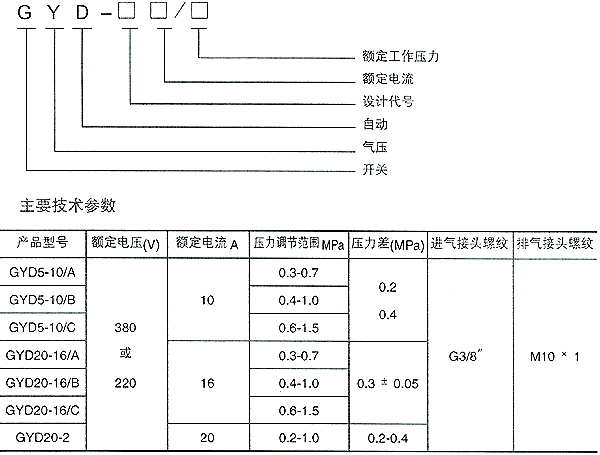
Product model and meaning
Installation and Debugging
1. The switch should be installed vertically with a tilt angle not exceeding 10 degrees.
2. The switch is used for the air compressor, and its intake joint is directly connected to the air storage tank, while the exhaust joint is connected to the cylinder exhaust chamber. (Using 6mm diameter purple steel pipe)
3. The switch is used for water pressure control, and the intake connector is directly connected to the water pressure container (without an exhaust connector). When wiring, do not disconnect or deform the wiring terminal.
4. The switch should be reliably grounded.
5. Debugging: Open the plastic casing, rotate the pressure adjustment screw according to the specifications on the nameplate, and try to adjust the pressure on both sides to be consistent. After starting up, refer to the pressure indicated on the pressure gauge. Pay attention to electrical safety during debugging, and it is strictly prohibited to fall when installing or removing the casing.
6. After using for a period of time, check the contacts for dust accumulation and burning. If burning is found, use a full phase sandpaper to polish or replace them in a timely manner.
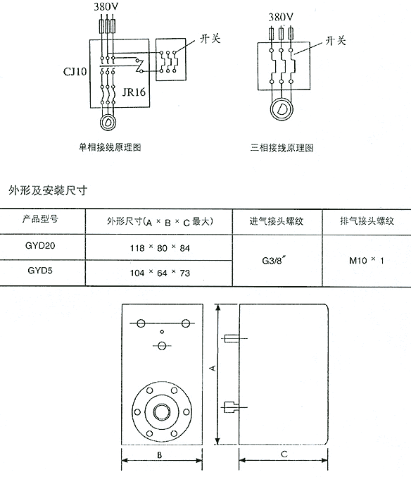
Circuit wiring (see figure below)

 Your location:Home → instrumentation and meters → Pressure gauge → pressure switch → GYD series air pressure switch

 Zoom in on the image
 Related Products:
 AL-KO-C1000 Large screen display intelligent ..
 Electrical instruments
  Micro pressure gauge
 沪公网安备31010702003255号
