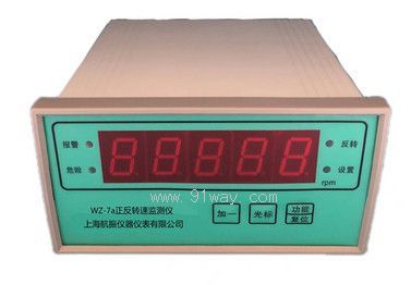
WZ-7a Reverse Speed Detection Monitoring and Protection Table
In most cases, the axis of the machine only rotates in one direction, so monitoring the forward speed of the machine is sufficient. However, for some machine operations, such as starting and stopping, the rotor may rotate in the opposite direction, causing extremely serious damage to the machine. Therefore, identifying reverse rotation and providing parking protection are also essential for monitoring.
The intelligent reverse speedometer identifies and protects the reverse rotation of the machine's shaft, which is carried out simultaneously in monitoring the mechanical speed. It can receive the phase provided by two speed sensors for comparison and make directional judgments. It has both speed measurement and reverse protection.
The input signal of the instrument comes from two speed sensors. The non-contact sensor probe is installed radially with appropriate clearance at the shaft convex or groove or speed measuring gear plate, facing the sensing body. The two sensors are installed at a certain angle, which has certain application requirements for the modulus, number, and distribution of the speed measuring gear plate or measuring teeth of the machine.
Main functions of WZ-7a anti rotation speed detection monitoring and protection table
Realize intelligent processing: parameters such as range value, alarm value, and number of teeth can be set through buttons
Alarm, danger, and reverse alarm functions are indicated by indicator lights on the panel, and relay output is provided through wiring terminals
The alarm delay adjustment range is 0-60 seconds to prevent false alarms caused by on-site interference
The rear panel has a current output terminal proportional to the speed value for recording output
Technical parameters
External power supply: 220VAC 50Hz 100mA
Input (power supply sensor power supply DC12V, if special voltage is required, please specify when ordering)
Signal: Acceptable
1. Two way eddy current sensor
2. Two way Hall sensor (sensor with built-in pull-up)
3. Two channel Hall integrated sensor (sensor with built-in pull-up)
Waveform: Square wave
Input impedance:>10K Ω
Range: -9999~9999 rpm
display
Display mode: Four digit 0.8-inch LED digital display
Display accuracy: ± 1 rpm
Photoelectric tube LED indication: normal, alarm, danger, reverse
Number of teeth: 3 teeth (using 2 independent sensors) or any tooth (using a dedicated reverse speed sensor)
Current output: 4~20mA active, output load ≤ 500 Ω
Alarm point range: 0~100% full scale, accuracy ± 0.1%
Relay sealing: epoxy resin, node capacity 7A/240VAC, normally open contacts
temperature range
Running time: 0 ℃~+65 ℃
Storage time: -30 ℃~+80 ℃
Relative humidity: up to 95%, non condensing
Dimensions: 160 * 80 * 160mm
Hole size: 152+1 × 74+1m
Button Introduction:
Add one "key: jump to the next parameter; Or in the parameter editing state: flashing bit plus 1;
'cursor' key: in parameter editing state: move one position left;
Function/Reset "button: Under the condition of manual alarm reset, when working normally, click this button to reset the alarm state; Under normal working conditions, press and hold this key for 5 seconds to enter the parameter setting mode; In the parameter setting state, press and hold this key for 5 seconds to return to normal working mode.
WZ-7a Reverse Speed Detection Monitoring and Protection Table Internal Parameter Table
|
parameter
logo |
Parameter Description |
setting
scope |
factory default |
Remark |
|
E1-- |
alarm threshold |
0~9999 |
three thousand and three hundred |
When the speed value is greater than or equal to the set value, the alarm indicator light will turn on, and the wiring terminal alarm terminal relay will output |
|
P1-- |
danger value |
0~9999 |
three thousand three hundred and sixty |
When the speed value is greater than or equal to the set value, the hazard indicator light will turn on, and the wiring terminal hazard terminal relay will output. The hazard value should be set greater than the alarm value. |
|
L1-- |
Range value |
0~9999 |
three thousand and five hundred |
The measurement value corresponding to the 20mA output should be within the range of alarm and danger |
|
H1-- |
number of teeth |
1~120 |
sixty |
Number of teeth on the speed measuring gear plate |
|
EE-- |
alarm delay |
0~60S |
one |
When the measured value is greater than or equal to the set alarm or danger value, the instrument enters the alarm state after a period of delay. Reverse speed alarm without delay |
|
AUTO |
Automatic |
0, 1 |
one |
1: Automatic alarm release 0: Manual alarm release |
|
PORC |
measurement method |
0, 1 |
0 |
0: Frequency measurement (tooth number "H1---" range 1-120) is suitable for high speeds, and the more teeth there are, the faster the response speed. Measurement range (1-99999rpm)
Stable time (S)=60 ÷ number of teeth
For example: 60 teeth, stable time of 1 second.
1: The measurement cycle (tooth number "H1---" range 1-10) is suitable for situations with few teeth, with a measurement range of 10-5000rpm. The response time is independent of the number of teeth. When the speed is greater than 60rpm, the instrument displays a speed response time of 1 second. When the speed is less than 60rpm, the response time (S)=60 ÷ actual speed; When the speed is less than 10 revolutions per minute, the displayed speed is 0. |
Parameter modification steps: Long press the SET button for 5 seconds until the digital display box is completely dark. Release the button to enter the parameter setting state. At this time, the digital display box will show "E1--". Press the "SET" button once to enter the alarm value setting. When you see the last digit of the digital display flashing, press the "<" button to select the digit that needs to be modified, and use the "+" and "-" buttons to modify the digit of the flashing digit. After the modification is completed, press the "SET" button to confirm and exit the alarm setting state. If you need to modify other parameters, you can press the "+" and "-" keys under the parameter name to enter other parameters. After setting up, press and hold the "SET" button for 5 seconds to save all parameters and return to the working state.
The installation of sensors should pay attention to the following points:
1. Install two probes at a 90 degree angle, with one sensor centered on the radial centerline of the tooth tip and the other sensor centered on the intersection of the tooth tip and valley.
There is a certain relationship between the forward and reverse directions of gears and the installation of sensors. After connecting the probe, pull the gear in the direction of normal rotation. If the instrument generates a reverse alarm signal, swap the INA and INB signal lines. If there is no reverse alarm signal, it indicates that the connection is correct.
The installation gap between the probe and the tooth tip is between 1 ± 0.2mm.
4. The modulus of the speed measuring gear plate is ≥ 1.5, and the gears are evenly distributed; The length of the tooth crest and tooth valley should be as equal as possible.
1. The sensor should be facing the axis, and there should be at least one keyway on the axis surface.
There is a certain relationship between the forward and reverse directions of gears and the installation of sensors. After connecting the probe, pull the gear in the direction of normal rotation. If the instrument generates a reverse alarm signal, swap the INA and INB signal lines. If there is no reverse alarm signal, it indicates that the connection is correct.
The installation gap between the probe and the tooth tip is between 2 ± 0.2mm.
4. The modulus of the speed measuring gear plate is ≥ 1.5, and the gears are evenly distributed; The length of the tooth crest and tooth valley should be as equal as possible.
Installation of instruments
This instrument is installed on the wall and can be installed on site or inside the instrument protection box. When installing, simply fix the supporting installation plate to the instrument, make holes according to the size shown in the figure, and then fix the instrument. Connect the wires again according to the instrument wiring diagram.

 Your location:Home → instrumentation and meters → tachometer → tachometer → WZ-7a Reverse speed detection monitoring and protection table

 Zoom in on the image
 Related Products:
 JYD100L-8/4 type three-phase dual speed async..
 Electrical instruments
  tachometer
 沪公网安备31010702003255号
