
 Your location:Home → instrumentation and meters → Electrical instruments → SENECA Transducers → CK-R/I Resistance/Current Converter
 |
Product name: | CK-R/I Resistance/Current Converter | |||||
| specification: |   Zoom in on the image Zoom in on the image |
||||||
| Category: | instrumentation and meters -- SENECA Transducers | ||||||
| |
Price: | factory price | |||||
| Brand: | Shanghai | ||||||
| Place of Origin: | China | ||||||
| |
Available Quantity: | batch | |||||
| delivery cycle: | Spot goods (or inquire by telephone) | ||||||
 |
|
||||||
CK-R/I resistor/current valve position converter is a potentiometer that uses an electric actuator as valve position feedback to convert the resistance change value into a 4-20mA DC valve position current signal output, which is used for indicating and controlling the valve position opening. It is widely used in angular and linear electric actuators.
1、 Input:
If it is one of the 500 Ω~5K Ω potentiometers, the potentiometer used for valve position feedback in electric actuators is usually 1K. Please specify the resistance value of the potentiometer used when ordering.
2、 Output:
4~20mA DC. Used for valve position indication and control.
3、 Power supply:
Usually 220V, special requirements can be customized.
4、 Transformer dimensions:
The length, width, and height are 80 × 50 × 30mm
5、 Wiring diagram of resistor/current converter and electric actuator
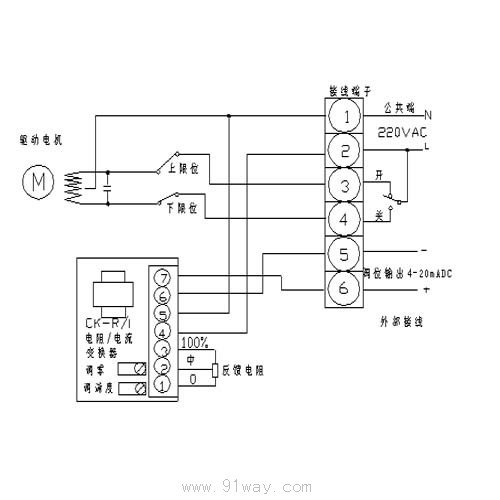
6、 Debugging methods for resistance/current converters
1. Only after ensuring the correct wiring (especially the 220V power cord cannot be connected incorrectly), can the power test be conducted.
2. When the middle tap of the input potentiometer is at 0%, adjust the output 4mA zero point. Zero adjustment is carried out using the zero potentiometer of the valve position transmitter. When turned clockwise, it can increase the output current, and vice versa.
3. When the middle tap of the input potentiometer is at 100%, adjust the input 20mA range transmission. The range adjustment is carried out using the range potentiometer of the valve position transmitter. Turning clockwise can increase the input current, and vice versa.
4. Repeat steps 2 and 3 until 0% and 100% correspond to the 4-20mA output standard, and the debugging is complete.
5. Each time the potentiometer on the valve position transmitter is adjusted, it should be gently adjusted. If no change is found in the input, the adjustment direction should be changed (for example, clockwise to counterclockwise) and the adjustment of that input point should be immediately stopped and changed to another input point (for example, if it was originally zero adjustment, it should be changed to range adjustment).
6. If it cannot be adjusted due to disorder, the middle tap of the input potentiometer can be placed at a position greater than 0% and less than 100% as a 4-20mA output for trial adjustment. After adjustment, it can be returned to 0% and 100% for correct adjustment.

 Related Products:
 J550XFS3242 type dual channel rotary transmit.. J540XFS6443 type dual channel rotary transmit.. J410XFS6443A,J410XFS6443B,J410XFS6443C type r.. J332XFS6443 type dual channel rotary transmit.. J303XFS6443 type dual channel rotary transmit.. J260XFSW6411 type dual channel rotary transmi.. J250XFS6442,J250XFS6442A type dual channel ro.. J250XFS1-6C,J250XFS1-6D type dual channel rot.. 250XFS1-6A,250XFS1-6B type dual channel rotar.. J212XFS001 type dual channel rotary transmitt.. Related articles:
 Electrical instruments
  Q meter bridge ammeter voltmeter Voltammeter frequency meter power meter electricity meter multimeter clamp meter ohmmeter phase sequence meter electroscope oscilloscope Distortion meter Load devices Panel instrument power meter L and C meter Internal Resistance Tester Withstand Voltage Tester signal generator signal isolator SENECA Transducers
  Voltage loss timer T_characteristic instrument Digital Display Instrument Temperature Instrument Humidity meter Pressure gauge flow meter analytical instrument Level instrument tachometer Recording instrument weighing instrument Specialized instruments
 Home|Quality Commitment|Ordering|Payment method|product delivery|support|Disclaimer|Contact Us
Copyright®2011 www.91way.com Copyright.
Phone:+86-21-66770508 +86-13916500500 Fax:+86-21-66108310
Email:91way@163.com Wechat:40606422
沪ICP备2021005791号  沪公网安备31010702003255号

