I. Overview
The XP05 vibrating string frequency (thermometer) is another practical civil engineering testing instrument developed after the XP99 and XP02 vibrating string frequency instruments. Its characteristic is that according to the construction monitoring needs of reinforced concrete, it can measure force, pressure, and strain for vibrating wire sensors, as well as temperature for digital temperature sensors, and both can achieve high accuracy from principle to practice.
It is worth mentioning that in the past, copper resistors and thermistors were mostly used as temperature measurement sensors in civil engineering. Due to their resistive nature, there are inconsistencies, non-linearity, and the influence of lead resistance. For sensor production units or users who lack good technology and are unprepared, it is difficult to ensure the accuracy of screening, calibration, and application.
The XP05 introduces and adapts to the new single bus digital temperature sensor device DSl8B20 launched by DALLAS in recent years, which represents the trend of temperature measurement devices and methods at room temperature in the future. Its temperature measurement range is -55 to+125 ℃, with a resolution of 0.0625 ℃ and an accuracy of ± 0.5 ℃ within the range of -10 to+85 ℃. It has many unique advantages, and here we focus on one of them, which is that it transmits digital signals instead of analog signals. As long as its signal is read, it is a temperature signal within its error range, and there will be no error caused by wire resistance or other reasons. Therefore, within the recognized accuracy range of ± 0.5 ℃, this component can be used without screening and calibration, which greatly facilitates practical work such as wiring and packaging for factories and users. Of course, if conditions permit, screening it will result in higher accuracy.
In order to promote the application of XP05 vibrating string frequency meter, we can also provide packaged temperature sensors or their packaging technology with DSl8B20 as the core for temperature measurement.
The motivation and application scenarios of XP05 vibrating string frequency (thermometer) mainly include the following two aspects:
① In terms of improving the measurement accuracy of vibrating wire sensors, the tensile stress δ experienced by the string in vibrating wire sensors is a single valued function of the natural frequency f of the vibrating wire, which can be characterized as: δ=K △ F
When the sensor is used in situations where there is a significant change in temperature, the above equation should be: δ=K △ F+b △ T+B
In the formula, k represents the calibration coefficient
Δ F represents the frequency modulus change, i.e. fn fo
B - Temperature compensation correction coefficient
Δ T represents the temperature change, i.e. Tn - To
B - Calculate correction constant
Therefore, by adding only one core wire, the DSl8B20 can be installed inside the vibrating wire sensor. The XP05 can simultaneously measure the vibrating wire frequency f and the ambient temperature T, and substitute them into the above formula for correction to improve accuracy.
② In the construction of large volume concrete: In terms of monitoring, during the construction process of large volume concrete foundations and large reinforced concrete components, it is necessary to simultaneously track and monitor stress, strain, and temperature. At this time, the vibrating wire sensor and temperature sensor can be combined in structural form or distributed separately.
During the concrete pouring process, the continuous pouring rate and the time interval for layered pouring are determined based on the monitoring results of temperature and stress.
In the process of concrete curing, the temperature difference between the interior and surface of the concrete caused by hydration heat, as well as the temperature difference between the surface and the air, should not exceed 25 ℃, in order to avoid stress cracks caused by the expansion and contraction changes of the concrete volume.
Observe that the uneven temperature stress caused by external factors such as sunlight does not exceed the safety limit of concrete structural components.
The XP05 vibrating string frequency meter fully utilizes single-chip microcomputer technology, tightly integrating software and hardware technology. It adopts equal precision measurement method in frequency measurement and redundancy verification method in temperature measurement, thus ensuring the accuracy of test results.
2、 Technical indicators
1. Measurement range: frequency 300-6000Hz
Cycle 166-3333 μ s
Temperature -55~+125 ℃
2. Measurement accuracy: Frequency 0.01%
Temperature ± 0.5 ℃ (-10~+85 ℃)
3. Display digits and resolution:
Frequency: Four digit integer, one decimal, ± 0.1Hz
Cycle: Four digit complex number, one decimal place, ± 0.1 μ s
Frequency squared: an eight digit integer
Temperature: Three digit integer, three decimal places, ± 0.062 ℃
4. Applicable sensors: The amplitude of the excited signal from the vibrating wire sensor is ≥ 300 μ V,
Duration ≥ 500ms
Temperature sensor DSl8B20, wire K ≤ 200m
5. Power supply: 6V1.3Ah sealed lead-acid battery, power consumption ≤ 45mA
6. Working environment: Temperature -5 ℃+45 ℃, relative humidity 30%~85%
7. Volume and weight: Aluminum container size 155 × 108 × 140mm, 1.8kg
3、 Instrument appearance and panel layout
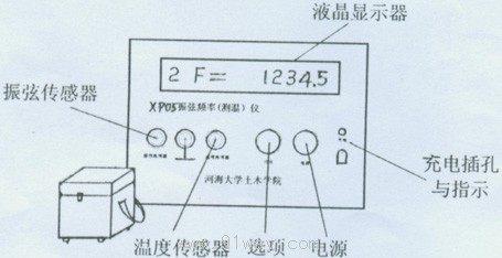
4、 Instructions for use
1. Open the instrument cover and connect the signal terminals of the vibrating wire sensor and temperature sensor to the left and right terminals respectively. The middle terminal is the common grounding terminal for these two sensors. Both types of sensor lead wires are divided into signal wires and ground wires. Incorrect or reversed connections will not damage the sensor, but the sensor will not work.
2. Press the "Power" button, and the LCD will display "One HEHAl One" and flash. Then press the "Project" selection button to enter each reading in sequence. The project sequence and reading content are shown in the table below:
| sequence |
code name |
meaning |
Display reading |
unit |
| one |
C |
temperature |
X X X·X X X |
℃ |
| two |
F |
frequency |
X X X X·X |
Hz |
| three |
FF |
Frequency squared |
X X X X X X |
- |
| four |
t |
Cycle |
X X X X·X |
μs |
| five |
U |
Excitation high voltage |
X X X |
V |
| six |
b |
battery voltage |
X·X X |
V |
3. The fourth "=" symbol from the left on the LCD display flashes once, indicating that it is vibrating or reading once. When switching to another sensor, the power switch is optional.
4. The 5th and 6th items are self-test of the high-voltage circuit and battery inside the device, independent of external sensors or signals.
5. When data cannot be read normally due to sensor damage, poor quality, or short circuit or open circuit of its leads, the following prompt will appear:
| Fault prompt |
Possible reasons |
| Err0 |
Temperature sensor internal or lead short circuit |
| Err1 |
Temperature sensor internal or lead open circuit |
| Err2 |
The temperature reception data has been verified to have errors, such as sensor water leakage and excessively thin and long leads |
| Err3 |
The vibrating wire sensor is damaged or of poor quality, causing short circuits or open circuits in the leads, resulting in the inability to measure the signal |
| Err4 |
Detected frequency signal but higher than 6KHz or measured battery voltage has been charged to 6.5V or above. |
5、 Precautions
1. When measuring the vibrating wire sensor in items 2-4 of this instrument, please do not touch the red and black crocodile clips connected to the left side line at the same time to avoid slight electric shock caused by high excitation voltage.
2. When the battery voltage is below 5.5V, a low voltage prompt of "one bAtt one" will appear after turning on the device. Although it can still be used at this time, it should be charged promptly for about 8 hours. Please turn off the power switch when charging. When sufficient, the charging indicator light will dim or turn off, and the instrument can be used continuously for about 16 hours thereafter.
3. The habit of charging after use should be adopted for future use. If the instrument is not used for a long time, it should be stored with sufficient electricity and recharged once every quarter. If the battery is found to be fully charged and used up immediately, it is likely that the battery has failed. At this point, you can open the lower cover of the instrument and replace the 6V1.3Ah battery. When installing a new battery, attention should be paid to polarity and prevent the positive terminal of the battery from colliding with the metal casing.
4. When the vibrating wire sensor is packaged together with DSl8B20, a three core sheathed cable can be used. When DSl8B20 is packaged separately, a universal two core wire or two core sheathed wire can be used. If the lead wires on the ground are long and there may be strong electromagnetic interference during measurement, it is necessary to use shielded cables with sheaths.
5. The transmission distance of the digital signal of the temperature sensor is related to the wire diameter, and it is required that the cross-sectional area of the lead wire diameter is not less than 0.3mm2. When the length of the lead exceeds 100m, it is necessary to test connect the long lead and correctly read the data before burying or laying it in batches.
6. If higher temperature measurement accuracy is desired, simply immerse all packaged temperature sensors in the same bucket of water, measure the average temperature, and then calculate the inherent deviation one by one as a reference correction value for future use.
7. LCD displays should avoid high temperatures and direct sunlight. Especially in summer, the scorching sun can easily cause LCD aging. Do not place hard objects inside the box cover to avoid squeezing the LCD and scratching the panel. Normally, the instrument panel and casing should be kept clean to prevent the entry and contamination of water vapor, soil, and dust.
6、 Connection with the selection box (hub box)
When testing or calibrating multiple vibrating wire sensors or temperature sensors, if the leads can be concentrated in one place, the XD20S manual point selection box can be used for measuring point switching to facilitate measurement. Each box of XD20S can accommodate 20 measuring points, and every 10 measuring points and one neutral position are switched by a rotary switch. The XP05 vibrating string frequency meter can be used by simply connecting the sensor terminals to one or several XD20S point selection boxes.
7、 Accessories of this instrument
1 set of 12V charger with crocodile clip connection cable
8、 Appendix Related Instruments
XP02 vibrating string frequency meter, with the same external volume, can measure the frequency of vibrating strings and is equipped with waveform output terminals for engineering testing, production debugging and screening of vibrating string sensors. XP99 vibrating string frequency meter, multifunctional type, equipped with rigid XD20X automatic point selection box, can achieve unmanned multi-point automatic scheduled inspection and store frequency readings, and can also send memory data to the computer. It can also form a real-time online measurement system under computer control.

 Your location:Home → instrumentation and meters → Specialized instruments → Engineering instruments → XP05 type vibrating wire frequency (thermometer)

 No image available
 Related Products:
 Electrical instruments
  Vibration meter
 沪公网安备31010702003255号

