
 Your location:Home → instrumentation and meters → Pressure gauge → pressure gauge → YXG-150-Z Anti vibration induction contact pressure gauge
 |
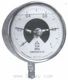
Product name: | YXG-150-Z Anti vibration induction contact pressure gauge | |||||
| specification: |   Zoom in on the image Zoom in on the image |
||||||
| Category: | instrumentation and meters -- pressure gauge | ||||||
| |
Price: | factory price | |||||
| Brand: | Shanghai | ||||||
| Place of Origin: | China | ||||||
| |
Available Quantity: | batch | |||||
| delivery cycle: | Spot goods (or inquire by telephone) | ||||||
 |
|
||||||
| model |
schematic diagram |
Contact type | The position of the control panel when it changes with the indicator needle | Equivalent contact point |
| YXG-150-Z21 |  |
upper and lower limits | 1. The control panels are all located inside the induction switch. 2. When the indicator needle moves up (or down), the control chip of the upper limit contact (lower limit contact) exits the sensing switch. |
1. Both contacts are disconnected, resulting in high impedance output 2. Connect the upper limit contact (lower limit contact) and output low impedance |
| YXG-150-Z11 | 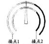 |
Double upper limit | 1. The control panels are all located inside the induction switch. 2. When the indicator pin goes up, the control pads of contacts 1 and 2 exit the induction switch in sequence. |
1. Both contacts are disconnected, resulting in high impedance output 2. Connect contacts 1 and 2 in sequence to output low impedance. |
| YXG-150-Z22 | 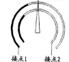 |
Double lower limit | 1. The control panels are all located inside the induction switch. 2. When the indicator pin descends, the control pads of contacts 2 and 1 exit the induction switch in sequence |
1. Both contacts are disconnected, resulting in high impedance output 2. Connect contacts 2 and 1 in sequence to output low impedance. |
| YXG-150-Z1 | 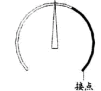 |
Single upper limit | 1. The control panel is located inside the induction switch. 2. When the indicator pin goes up, the contact control piece exits the induction switch. |
1. Contact disconnected, high impedance output 2. Connect the contact and output low impedance. |
| YXG-150-Z2 |  |
Single lower limit | 1. The control panel is located inside the induction switch. 2. When the indicator pin descends, the contact control piece exits the induction switch. |
1. Contact disconnected, high impedance output. 2. Connect the contact and output low impedance. |
|
Note: In the diagram | ||||
| Contact status | Equivalent contact point (YXG-K output terminal) |
Induction switch status | Output current (Instrument output terminal) |
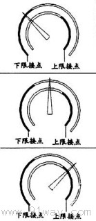 |
Lower limit contact point |
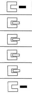 |
≥3mA (3, 4) |
Upper limit contact point |
≤1mA (1, 2) | ||
Lower limit contact point |
≤1mA (3, 4) | ||
Upper limit contact point |
≤1mA (1, 2) | ||
Lower limit contact point |
≤1mA (3, 4) | ||
Upper limit contact point |
≥3mA (1, 2) | ||
| Note: Output terminals 1 and 2 with dual upper or lower limits are contact 2, while terminals 3 and 4 are contact 1 | |||

 Related Products:
 AL-KO-C1000 Large screen display intelligent .. Y-BF-T series stainless steel belt rear press.. YTW Series High Temperature Pressure Gauge YT.. XMT-B Intelligent furnace negative pressure g.. YM-40Z Fire pressure gauge YM-25Z Fire pressure gauge YM-36 Fire pressure gauge FT type fire pressure gauge F72-DC-Mpa Marine pressure gauge YJB-1500 Compensation micro pressure gauge Related articles:
 Electrical instruments Digital Display Instrument Temperature Instrument Humidity meter Pressure gauge
  Micro pressure gauge pressure gauge
  Diff pressure gauge tensiometer pressure reducer pressure switch Diff pressure switch Tension controller tension sensor pressure sensor Pressure transmitter pressure controller Diff pressure transmitter Diff pressure controller flow meter analytical instrument Level instrument tachometer Recording instrument weighing instrument Specialized instruments
 Home|Quality Commitment|Ordering|Payment method|product delivery|support|Disclaimer|Contact Us
Copyright®2011 www.91way.com Copyright.
Phone:+86-21-66770508 +86-13916500500 Fax:+86-21-66108310
Email:91way@163.com Wechat:40606422
沪ICP备2021005791号  沪公网安备31010702003255号


