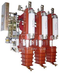
FKN12A-12D compressed air load switch and FKRN12A-12D series compressed air load switch fuse combination device are new series of switchgear developed by our company, suitable for controlling and protecting power equipment such as transformers, cables, overhead lines, etc. in three-phase distribution systems of 12KV and below; Specially suitable for terminal substations and box type substations in urban and rural power grids, as well as for control and protection of ring networks and dual radiation power supply units The FKN12A-12D series compressed air load switch can switch between load current and overload current FKRN12A-12D series compressed air load switch fuse combination device can switch load current, overload current, and short-circuit current of the circuit. 1-2 This series of products has the characteristics of compact structure, reasonable design, reliable interlocking, and high insulation level. Its switching and closing adopt vertical direct action mode; The opening and closing speed of the spring energy storage operating mechanism is not affected by the magnitude of the operator's operating force; The arc is extinguished inside the bell shaped insulation cover, and the free gas during arc ignition will not cause a decrease in the insulation strength between phases or to ground An organic transparent insulation cover is installed between the bell shaped cover and the support (i.e. between the switch isolation fracture) to completely isolate the charged body and improve the protection level of the ring main unit Reliable mechanical interlocks are installed between the load switch and the grounding switch, and mechanical interlocks between the switch panel and the cabinet are also installed on the switch panel. These interlocks are simple and effective, ensuring that there will be no misoperation or accidental contact with live parts
The FKN12A-12D series load switch adopts copper tungsten alloy arc contacts and plum blossom shaped main contacts, which make the switch conductive reliably, have a long electrical life, easy maintenance, convenient operation, and reliable operation. It is highly praised by users
The design and manufacturing of FKN12A-12D series load switches comply with the following standards: GB3804<<3-63KV AC high voltage load switches>>GB16926<
>GB1985<>IEC665<>IEC420<>
Technical parameters of FKN12A-12D series load switch
FKN12A-12D series load switch, FKRN12A-12D series load switch - fuse combination electrical device technical parameter number name unit FKN12A-12D FKRN12A-12D
1 Rated voltage KV 12 12
Rated frequency Hz 50 50
3 Rated current A 630 125
4 rated insulation level 1 mm power frequency withstand voltage to ground, phase to phase KV 42
Isolation fracture 48 48
Lightning withstand voltage (peak) to ground, phase to phase 75 75
Isolation fracture 85 85
5 rated short-circuit withstand current (thermal stability current) load switch KA 20 grounding switch 20
6 rated short-circuit duration (thermal stability time) load switch S 4 grounding switch 2
7 rated short-circuit closing current (peak) KA 50
8 rated breaking current active load breaking current A 630
Closed loop disconnect power supply 630 5% active load disconnect current 31.5 cable charging current 10 disconnect no-load transformer capacity 1250
Rated short-circuit switch breaking current (current limiting fuse) KA 31.5
10 rated transfer current A 1200
11 Mechanical service life 2000 2000 4-2 Mechanism characteristics are shown in Table 2: Serial number name Unit data
1. Fracture moment mm ≥ 150
The center distance between two phases is 210 ± 2
3 phase air gap ≥ 125
4 strokes 210 ± 4
5 overtravel ≥ 41
6. Three phase closing with different synchronization ms ≤ 10
7. Three phase closing with different periods ≤ 5
The inherent opening time of the 8-point excitation release is 40-65
9. Main circuit resistance U ≤ 300 4-3 FKRN12A-12D series load switch - selection of rated current of current limiting fuse for fuse combination electrical equipment. The reference number for transformer capacity selection is shown in Table 3. Transformer capacity (KVA) 100 125 160 200 250 300/315 400 500 630 750/800 1000 1250
Rated current of fuse (A) 16 16 20 25 31.5 40 50 63 60 80 100 100 125
4-4 Optional attachments are shown in Table 4. Main parameters for user selected attachments
Electric operating mechanism
The compressed air switch can be equipped with an electric operating mechanism for remote control of opening and closing Rated voltage: AC220V, DC220V, DC48V, DC24V
Rated current: 0.8A 3.6A 7.2A
Rated power: 120W
Energy storage time: 2-4 seconds
Work schedule: S2/1min
Rated voltage of shunt release: AC220V
Internal resistance: 32
Overcurrent release 5A
Auxiliary contact
Both load switch and grounding switch can be optionally equipped with a maximum withstand voltage of AC500V
Maximum allowable current value: 5A
Standing auxiliary contacts: one open one closed, two open two closed, three open three closed, four open four closed
Interlocking head between switch cabinets
This series of load switches can be equipped with specially designed interlocking heads to achieve interlocking between two load switches with interlocking heads. If one switch is opened, the other switch will automatically close, and the interlocking head cannot be removed after closing
5. FKN12A-12D series load switch appearance and installation dimensions
FKN12A-12D load switch appearance, installation dimensions, and installation methods are shown in Figure 1, Figure 2, and Figure 3. Note: Figure 1 shows the left side installation operation, and the side inverted left operation; Side inverted left operation, side mounted left operation Figure 2 shows the front left operation and the front inverted operation Figure 3 shows the front installation left operation and the front inverted left operation. The appearance, installation dimensions, and installation method of the 5-2 FKRN12A-12D series compressed air load switch fuse combination device are shown in Figure 4. Figures 5, 6, and 7 show the external dimensions and installation method of the electric mechanism, as shown in Figure 8. Note: Figure 4 shows the side installation left operation and the side inverted left operation; Side inverted left operation, side mounted left operation Figure 5 shows the front right operation and the front inverted right operation Figure 6 shows the left operation for front installation and the left operation for front inversion Figure 7 is a schematic top view of the right operation installation for front installation. Figure 5-3 shows the installation of switches, panel interlocking, and hole opening. Figure 9.6. Packaging, lifting, and unpacking inspection. 6-1 Packaging, lifting requirements: The load switch should be packaged as a single unit when it leaves the factory. When lifting is needed during transportation, it should be carried out according to the position marked on the outside of the packaging box. 6-2 Unpacking inspection: After receiving the product, the user should immediately inspect the packaging and transportation of the switch to see if there is any damage, damaged accessories, and whether they match the packing list; Check if the product model and specifications are the same as the order. 6-3 Factory Document Main Attachment A) Installation and Use Manual;
B) Product qualification certificate;
C) Product factory test records;
D) Packing list;
E) Schematic diagram of switch wiring;
F) Operating handle;
G) Interlocking head of cabinet door; 6-4 Storage
The product should be stored indoors in a well ventilated, dry environment without severe vibration or corrosive gases. It should be protected from rain, moisture, and direct sunlight. Before installation, the product should be checked for completeness and loose fasteners
B) The installation surface of the switchgear must be in good contact with the installation surface of the switch. If there is a gap, a gasket must be added to level it. Do not forcefully lock it with fasteners
C) The installation dimensions of the busbar connected to the switch inlet and outlet must be accurate and cannot be forcibly pulled or tightened. 8. When maintaining the fuse to break and impact the circuit breaker, it is necessary to replace the three-phase fuse with the same model and specification. 9. Ordering instructions: Users should indicate the model FKN12A-12 FKN12A-12D FRKN12A-12D when ordering
Installation method: Side mounted, front mounted, inverted
Operation mode: manual electric
Operation direction: left operation, right operation
Partial excitation trip (rated voltage) 110V 220V
Auxiliary switches 4a 4b
Note: When using a lower incoming line, the load switch is not equipped with a grounding knife. Please specify when ordering When the two incoming load switches adopt mechanical interlocking or program interlocking, please specify when ordering