
 Your location:Home → Pump valve fittings → actuator → valve positioner → ALS series valve limit switch
 |
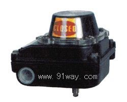
Product name: | ALS series valve limit switch | |||||
| specification: |   Zoom in on the image Zoom in on the image |
||||||
| Category: | Pump valve fittings -- valve positioner | ||||||
| |
Price: | factory price | |||||
| Brand: | Shanghai | ||||||
| Place of Origin: | China | ||||||
| |
Available Quantity: | batch | |||||
| delivery cycle: | Spot goods (or inquire by telephone) | ||||||
 |
|
||||||
Technical requirements for limit switches of ALS series valves
Protection level: IP65 (intrinsic safety type) IP67 (shell protection type)
Easy contact: 6A/24VDC (DC)
10A/220V AC (AC)
Environmental temperature: -35 ℃~+70 ℃
Wiring port: 2-G1/2“
Placement angle: 0 ° to 90 ° angular travel
0 °~180 ° (adjustable)
Position indication: on yellow, off red
Dimensions: 120 × 120 × 103mm
Weight: Approximately 1.6Kg
IP65 Kg
IP67 Kg
Working principle of limit switch
The valve position angle displacement detected by the ALS series valve limit switch box is rotated by the shaft connection or feedback rod, causing the cam to trigger the micro switch, thereby closing or opening the contacts of the switch component. The switch signal is transmitted to the outside through the wiring terminal and displayed through the pointer.
Installation and use of limit switches
1、 Move the valve to the closed position and adjust the red cam to output a signal from the "close" switch.
2、 Move the valve to the open position and adjust the yellow cam to output a signal from the "on" switch.
3、 Make sure the limit switch signal is reliable by running the valve back and forth a few times.

Home|Quality Commitment|Ordering|Payment method|product delivery|support|Disclaimer|Contact Us
Copyright®2011 www.91way.com Copyright.
Phone:+86-21-66770508 +86-13916500500 Fax:+86-21-66108310
Email:91way@163.com Wechat:40606422
沪ICP备2021005791号  沪公网安备31010702003255号





