The OWF series coupling capacitors are mainly used in high-frequency carrier communication, measurement, control, protection, and energy extraction devices for power frequency AC transmission lines.
structural performance
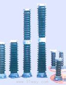
The OWF series coupling capacitor consists of a core group, a ceramic sleeve, an expander, and other components. The core assembly consists of several polypropylene films, capacitor paper, and aluminum foil rolls connected in series; The outer shell is composed of a large cover made of porcelain sleeve and steel plate, a plate bottom, and a sealed oil resistant rubber ring.
The frequency is 50Hz, and the capacitor operates for a long time under the condition of adding 30-5000KHz communication waves at 1.2 times the rated voltage. When used in a star point effective grounding system, it can run continuously for 30 seconds at 1.5Un; when used in a star point non effective grounding system with automatic disconnection of ground faults, it can run continuously for 30 seconds at 1.9Un; when used in a star point non effective grounding system without automatic disconnection of ground faults, it can run continuously for 8 hours at 1.9Un.
working environment
(1) Capacitors are outdoor devices used for ambient temperatures ranging from -50oC to+50oC.
(2) The altitude of the installation and operation area shall not exceed 1000m. (Special design is available for high-altitude areas)
(3) The wind speed in the installation and operation area shall not exceed 150km/h, and the seismic intensity shall not exceed 8 degrees.
Installation Instructions
Suspend and use ordinary capacitors with a voltage of ≤ 35kV. When used for suspension, the hanging ring screws on the upper cover should be used for suspension, with the upper cover as the high-voltage end and the bottom plate as the low-voltage end.
Stand up and use ordinary capacitors with a voltage of ≤ 35kV. When used for standing, the bottom should be equipped with a qualified OZ-35 insulation bracket; The upper cover is the high-voltage end, and the capacitor bottom plate is the low-voltage end. The four corner circular holes of the iron plate under the bracket are used for installing and fixing screws.
Each type of 220kV capacitor is composed of two 110kV capacitors connected in series, with one section with a cast iron base as the lower section. Tighten the upper section bottom plate and the lower section top cover together with bolts. The four corner circular holes on the base are fixed screw holes. When multiple units are used, they should be paired according to their factory codes and not confused to avoid affecting the technical specifications of the capacitors.
Technical performance of OWF series coupling capacitors:
1. Technical parameters of coupling capacitors for 35KV stations
1. Name: Coupling Capacitor Model: OWF-350 √ 3-0.0035
2. Model: OWF.
3. Industrial frequency: 50Hz.
4. Carrier frequency range: 40-500kHz.
5. Rated voltage of the line: 35/kV.
6. Rated capacitance: 0.00035 Uf.
7. The deviation of capacitance value shall not exceed+10% -5%.
8. The creepage distance shall not be less than 20mm/kV.
9. The insulation level should comply with the provisions of GB311.1-83 "Insulation Coordination of High Voltage Transmission Equipment".
10. The tangent value of the loss angle (at 20 ℃) shall not exceed 0.0015.
11. The stray capacitance value between the low-voltage terminal and the ground shall not exceed 200PF, and the stray conductivity value shall not exceed 20us.
12. Weight: 45kg
Technical parameters of coupling capacitors for 110KV power stations
1. Name: Coupling Capacitor Model: OWF-110 √ 3-0.0066/0.01
2. Model: OWF.
3. Industrial frequency: 50Hz.
4. Carrier frequency range: 40-500kHz.
5. Rated voltage of the line: 110/kV.
6. Rated capacitance: 0.0066/0.01.
7. The deviation of capacitance value shall not exceed+10% -5%.
8. The creepage distance shall not be less than 20mm/kV.
9. The insulation level should comply with the provisions of GB311.1-83 "Insulation Coordination of High Voltage Transmission Equipment".
10. The tangent value of the loss angle (at 20 ℃) shall not exceed 0.0015.
11. The stray capacitance value between the low-voltage terminal and the ground shall not exceed 200PF, and the stray conductivity value shall not exceed 20us.
12. Weight: 170kg.
13. Installation method: seated.
Technical parameters of coupling capacitors for 220KV stations
1. Name: Coupling Capacitor Model: OWF-220 √ 3-0.005/0.0033
2. Model: OWF.
3. Industrial frequency: 50Hz.
4. Carrier frequency range: 40-500kHz.
5. Rated voltage of the line: 220/kV.
6. Rated capacitance: 0.005/0.0033Uf.
7. The deviation of capacitance value shall not exceed+10% -5%.
8. The creepage distance shall not be less than 20mm/kV.
9. The insulation level should comply with the provisions of GB311.1-83 "Insulation Coordination of High Voltage Transmission Equipment".
10. The tangent value of the loss angle (at 20 ℃) shall not exceed 0.0015.
11. The stray capacitance value between the low-voltage terminal and the ground shall not exceed 200PF, and the stray conductivity value shall not exceed 20us.
12. Weight: 330/320kg.
13. Installation method: seated.
Main technical parameters of OWF series coupling capacitors
|
serial number |
model |
rated voltage
(kV) |
Rated capacitance
(μF) |
Overall dimensions
L×B×H(mm) |
weight
(kg) |
|
one |
OWF35-0.0035 |
thirty-five |
zero point zero zero three five |
275×275×760 |
fifty-five |
|
two |
OWF110/√3-0.0066 |
110/ |
zero point zero zero six six |
485×415×1430 |
two hundred and ten |
|
three |
OWF110/√3-0.01H |
110/ |
zero point zero one |
485×415×1430 |
two hundred and fifty |
|
four |
OWF220/√3-0.005H |
220/ |
zero point zero zero five |
485×415×2700 |
four hundred and eighty |
OWF series coupling capacitors