
 Your location:Home → Pump valve fittings → actuator → valve positioner → ZXQ98 Electric valve manual locator
 |
Product name: | ZXQ98 Electric valve manual locator | |||||
| specification: |   Zoom in on the image Zoom in on the image |
||||||
| Category: | Pump valve fittings -- valve positioner | ||||||
| |
Price: | factory price | |||||
| Brand: | Shanghai | ||||||
| Place of Origin: | China | ||||||
| |
Available Quantity: | batch | |||||
| delivery cycle: | Spot goods (or inquire by telephone) | ||||||
 |
|
||||||
The ZXQ98 electric valve intelligent manual positioner (hereinafter referred to as the positioner) can be matched with potentiometers or standard current feedback electric actuators to accurately position various valves, with intuitive display and convenient operation. Widely used for precise control of electric valves in industries such as metallurgy, petrochemicals, building materials, machinery, cement, pharmaceuticals, food, brewing, papermaking, etc.
1、 Main features
Free choice of automatic/manual mode;
The unique TOYI input signal filtering algorithm effectively filters out spike pulse signals that are hundreds of times larger than the normal input signal range, while maintaining a sampling speed of 8 times per second and technical accuracy;
Multi parameter display, simultaneously displaying valve position measurement values and set values for easy observation and debugging;
Equipped with convenient functions such as automatic valve position calibration, electronic braking, anti frequent start, and locked rotor detection and control;
Convenient adjustment of positioning accuracy to ensure stable positioning and achieve one-step positioning function;
Positive/negative effects can be set and output with upper and lower limit limiting functions.
2、 Main technical indicators
Power supply: 100~240VAC, less than 8W (other power supply voltages can be customized)
Environmental temperature: 0-50 ℃, humidity 35-85%
Appearance and opening size: Width x Height x Depth 96 x 96 x 110mm
Opening: 91+1 × 91+1mm
Display range: 0.0-100.0%
Display accuracy: 0.1%
Positioning accuracy: The highest positioning accuracy is ± 0.1%
Acceptable feedback signal from electric actuator: Potentiometer: 500 Ω~5K Ω
Current: 4-20mADC
Input: Standard current/voltage: 4~20mA/1~5ADC (other input signals can be customized), input impedance 250 Ω
Output (with positive/negative effect selection and output upper and lower limit limiting functions):
① Output relay contact capacity: AC 250V, 3A
② Valve opening feedback signal proportional analog output 4-20mA
Parameters that can be set:
① Power on state ② Minimum set opening ③ Maximum set opening ④ Positioning accuracy ⑤ Parameters that can be calibrated for abnormal signal input actions or shielding:
① Actuator range zero position ② actuator range full position ③ input signal zero and full degree ④ output signal zero and full degree
Attention: The parameters are password protected, and the parameters are reserved for use by the factory
3、 Instrument panel
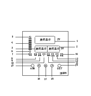
|
NO. |
Panel Text |
Content |
|
one |
PV |
Actual valve position opening display |
|
two |
SV |
External valve position setting value/manual setting value |
|
three |
Nothing |
The regular type is reserved for use, while the communication type displays the communication address number |
|
four |
Nothing |
The light column indicates the actual opening of the valve position |
|
five |
Nothing |
Indicate whether the actuator "on" relay is closed or not, it lights up when closed and goes out when disconnected |
|
six |
Nothing |
Indicate whether the actuator "close" relay is closed or not, it lights up when closed and goes out when disconnected |
|
seven |
AL1 |
Reserved for use |
|
eight |
AL2 |
Reserved for use |
|
nine |
AUTO |
Automatic status display light |
|
ten |
MAN |
Hard hand operation status display light |
|
eleven |
OUT1 |
Always on when automatic, flashing when operated with hard hands |
|
twelve |
OUT2 |
Reserved for use |
|
thirteen |
TXD |
Communication Indicator Light |
|
fourteen |
RXD |
Communication Indicator Light |
|
fifteen |
A/M |
Automatic/manual selection key, enter parameter setting key |
|
sixteen |
Nothing |
Reserved for use |
|
seventeen |
Number reduction key | |
|
eighteen |
Number increase key | |
|
nineteen |
SET |
Set button, communication type enters communication address setting |
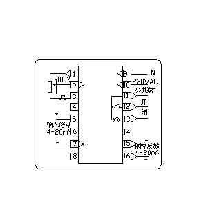
4、 Wiring method
The weak current signal line terminal is connected to a 1K Ω actuator feedback potentiometer. For example, 1, 2, and 3 are respectively connected to the three terminals of the feedback potentiometer inside the electric actuator. Among them, 2 is connected to the sliding arm of the potentiometer, 1 is connected to one end where the resistance between the actuator and the sliding arm decreases continuously when the actuator is turned on, and 3 is connected to the other end;
Terminals 5 and 7 are weak current signal line terminals, connected to 4-20mA input signals, used for automatic control of instrument actuators from fully closed to fully open, with 5 connected to positive and 7 connected to negative
Terminals 9 and 10: Instrument power supply, connected to AC 220V, preferably using isolated or purified power supply, and avoiding using the same power supply as the actuator (using a transformer, the secondary winding of the instrument power supply is suspended and not grounded).
Terminals 11, 12, and 13: Two relays with a capacity of AC250V, 3A are connected to the opening and closing terminals of the actuator. The relay contacts are in a normally open state. As the terminals are used to control the opening and closing of the electric actuator, their load is usually an inductive load. When the switch is disconnected, a high induced voltage will be generated, which will interfere with the operation of the instrument. Therefore, an appropriate resistor and capacitor series absorption protection circuit should be connected. Terminal 11 and the common terminal (COM) of the actuator are connected to L and N of the power supply, respectively.
Terminals 5 and 16 are weak current signal line terminals that output 4-20mA actuator position signals. They have photoelectric isolation, with 15 connected to positive and 16 connected to negative.
When the instrument leaves the factory, the input signal is calibrated according to the 4-20mA standard current signal. After connecting the instrument and the electric actuator according to the wiring terminal diagram of the instrument, the zero and full positions of the actuator need to be calibrated to ensure the normal operation of the instrument. The automatic calibration function of the instrument can conveniently calibrate the actuator.
Connect the electric actuator and power supply connection according to the instrument wiring terminal. Reasonable instrument wiring can make the instrument work more reliably. To reduce motor interference, the motor control line and feedback signal line of the electric actuator should be routed separately; The weak current signal line of the instrument should be as short as possible. If longer connections are necessary, shielded signal lines should be used, and the outer shield should be properly grounded with the control cabinet casing.

 Related Products: Related articles:
Home|Quality Commitment|Ordering|Payment method|product delivery|support|Disclaimer|Contact Us
Copyright®2011 www.91way.com Copyright.
Phone:+86-21-66770508 +86-13916500500 Fax:+86-21-66108310
Email:91way@163.com Wechat:40606422
沪ICP备2021005791号  沪公网安备31010702003255号





