
 Your location:Home → Pump valve fittings → actuator → valve positioner → ZXQ2003/ZXQ2004 series valve intelligent locator
 |
Product name: | ZXQ2003/ZXQ2004 series valve intelligent locator | |||||
| specification: |   Zoom in on the image Zoom in on the image |
||||||
| Category: | Pump valve fittings -- valve positioner | ||||||
| |
Price: | factory price | |||||
| Brand: | Shanghai | ||||||
| Place of Origin: | China | ||||||
| |
Available Quantity: | batch | |||||
| delivery cycle: | Spot goods (or inquire by telephone) | ||||||
 |
|
||||||
1. Overview
ZXQ2003 and ZXQ2004 electric valve intelligent locators are intelligent signal acquisition and control systems with industrial microcontrollers as the core. They are compact in size and can be installed in the junction box of the electric actuator or fixed outside in a DIN rail manner. They can directly receive 4-20mADC signals output by industrial instruments or computers (other input signal types can be customized before leaving the factory), and are matched with potentiometer feedback electric actuators to perform precise positioning operations on various valves or devices. They can freely calibrate the angle (or displacement) of the electric actuator, and output 4-20mADC actuator angle position (or displacement) feedback conversion signals. The lower and upper limit values of the actuator angle position can be accurately set by pressing three buttons. The locator uses three buttons to accurately set the lower and upper limit values of the actuator angle position. Operation, 9 LED lights can directly display the locator mode, 4-digit digital LED By using buttons to switch between displaying the actual opening value of the valve position, the set opening value of the valve position, and the temperature inside the locator housing, the operation is convenient.
2. Main technical indicators
Control accuracy: 0.1% -3.0% (adjustable through U4 parameter)
Can receive feedback signals from electric actuators: potentiometer 500 Ω -10K Ω
Can receive external control signals (DC): 4-20mA (1-5V, 0-10V, switch quantity, etc. customized before leaving the factory)
Input impedance: 250 Ω;
By modifying the U1 parameter, the following modes can be set: ① DRTA/forward action, RVSA/reverse action mode ② "Interrupt" mode when the input signal is interrupted - OPEN, STOP, SHUT
Optional: ① Controllable silicon output (AC, 600V, 25A)
② Relay output (AC, 250V, 10A) ◆ Please specify when ordering
Output actuator position signal: Low drift output 4-20mADC corresponds to actuator fully closed to fully open, signal completely isolated from input (photoelectric isolation), output load ≤ 500 Ω
Environmental temperature: 0-70 ℃, humidity: 35-85%
Equipped with over temperature protection function: When the temperature inside the locator shell is ≥ 70 ℃, the locator stops controlling the opening and closing of the actuator
Dimensions: ZXQ2003 77mm (bottom length) × 76mm (bottom width) × 51mm (height);
ZXQ2004 74mm (bottom length) × 57mm (bottom width) × 45mm (height)
The action range of the actuator corresponding to the input signal can be freely calibrated by pressing the button (usually calibrated as the fully closed or fully open position of the electric actuator)
Can set upper and lower limit points
Control function for actuator stalling detection: If the control actuator experiences stalling for 3-4 seconds, the locator will disconnect the control output for 1 minute; Repeatedly check and control until the blockage is eliminated.
Self adjustable accuracy can be set: If the actuator fails to position during operation and vibrates back and forth three times, the locator will automatically reduce the positioning accuracy by 1/1000 (i.e. original accuracy+1/1000) and repeatedly adjust it to the appropriate control accuracy. Set the parameter to U0 (000. x)
Password lock to prevent accidental operation
Anti actuator frequent startup function
Indicate the cause of the fault with an error code (E 0X)
Intelligent step distance adjustment and precise positioning based on input signal and actuator angle position
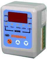
3. Locator panel
|
parameter
display |
one |
LED
Windows |
Switch between displaying the actual valve opening value, valve set opening value, locator shell temperature, and set parameters through buttons |
|
status
Instructions |
two |
OPEN |
Output control "on" relay closure |
|
three |
SHUT |
Output control "close" relay closure | |
|
four |
MANU |
Manual mode | |
|
five |
AUTO |
Auto Status | |
|
Mode indication MODE |
six |
DRTA |
In positive action mode, the input signal corresponds to the following output:
4mA - full position (usually calibrated as fully open) 20mA - zero position (usually calibrated as fully closed) |
|
seven |
RVSA |
In reverse action mode, the input signal corresponds to the following output:
4mA - Zero position (usually calibrated as fully closed) 20mA - Full position (usually calibrated as fully open) | |
|
eight |
OPEN |
The input signal interruption mode is "on", causing the actuator to open to the maximum opening limit | |
|
nine |
STOP |
The input signal interrupt mode is "stop", causing the actuator to stop at the current position | |
|
ten |
SHUT |
The input signal interruption mode is "closed", causing the actuator to open to the minimum opening limit | |
|
button |
eleven |
A/M |
Manual/automatic switch button, parameter entry modification and switching button |
|
twelve |
▲ |
The numerical increase key is also used to switch the display valve position setting opening value in automatic mode, and "on" in manual mode | |
|
thirteen |
▼ |
The numerical decrease key is also used to switch the display of the temperature inside the locator shell in automatic mode, and is "closed" in manual mode |
4. Wiring method
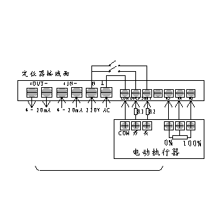
Connect the electric actuator and power supply wires according to the wiring diagram on the instrument terminal and instrument housing in the following figure. Pay attention to the polarity of the connection. To reduce motor interference, separate the motor control wire and feedback signal wire of the electric actuator; The weak current signal line of the instrument should be as short as possible. If longer connections are necessary, shielded signal lines should be used, and the outer shield should be properly grounded with the control cabinet casing.
The locator is connected to the electric actuator through a seven wire connector, where the GND terminal on the locator can be connected to the motor actuator housing or suspended; RO, RV, and RS are respectively connected to the three terminals of the feedback potentiometer inside the electric actuator. RV is connected to the sliding arm of the potentiometer, RO is connected to the end where the resistance between the actuator opening action and the sliding arm continuously decreases, and RS is connected to the other end; SHUT, OPEN, and COM are respectively connected to the closed, open, and COM terminals of the actuator servo motor.
Note: In order to reduce the current surge when the actuator starts and stops, a cement resistance of 4 Ω/5W is generally applied indirectly between "OPEN" and "CLOSE" and the "ON" and "OFF" in the actuator (as shown in R1 and R2 in the figure below).
Note: The locator COM, OPEN, and SHUT are active output terminals, and the output voltage corresponding to COM, OPEN, and COM, SHUT is the power supply voltage.
 Related Products: Related articles:
Home|Quality Commitment|Ordering|Payment method|product delivery|support|Disclaimer|Contact Us
Copyright®2011 www.91way.com Copyright.
Phone:+86-21-66770508 +86-13916500500 Fax:+86-21-66108310
Email:91way@163.com Wechat:40606422
沪ICP备2021005791号  沪公网安备31010702003255号





