The ZJ torque and speed sensor is installed between the power transmission shafts. It is used in conjunction with the TR type torque and speed power measuring instrument and the CZ type magnetic powder brake (WZ type eddy current brake) to measure the torque and speed power of various power and transmission machinery such as engines, motors, fans, compressors, hydraulic pumps, gearboxes, etc. in the range of 0-6000 revolutions per minute. Among them, ZJ is a sensor that outputs two voltage signals with phase difference through magneto electric transformation, and TR type is a single-chip measuring instrument with printing and display. The CZ type magnetic powder (eddy current) brake generates adjustable damping torque through excitation current, making it an ideal loader for complete power measurement. Please refer to the relevant instructions for the specific use of TR and CZ (WZ). Our company provides a complete set of dynamometer systems for turnkey projects.
2、 Working principle:
The ZJ torque and speed sensor mainly consists of four parts: torque shaft, magnetic detector, drum, and housing. The magnetic detector consists of two paired sets of internal and external gears, permanent magnets, and induction coils. The two ends of the external gear installation load torque shaft measurement section; Inside the internal gear drum, opposite to the external gear, a permanent magnetic steel is installed adjacent to the internal gear inside the drum. Permanent magnet steel, inner and outer gears form a circular closed magnetic circuit, and the induction coil is fixed inside the two end covers of the housing. Under the drive of the motor, the internal gear rotates along with the drum.
The internal and external gears are variable displacement gears that do not engage with each other. The tooth tip is determined by the working air gap, and the air gap is narrowest when the tooth tips of the internal and external gears are relative to each other, and widest when the tooth tips and grooves are relative to each other. When the internal and external gears rotate relative to each other, the tooth tips alternate with the tooth slots. When they rotate relative to each other by one tooth position, the working air gap undergoes a periodic change, and the magnetic resistance and flux of the magnetic circuit change accordingly. Therefore, an approximately sine wave voltage signal is induced in the coil, and the instantaneous value of the signal voltage changes in accordance with the relative position of the internal and external gears.
If the projections of the gears of two sets of detectors coincide with each other, the phase difference between the two sets of voltage signals is zero. During installation, the projections of the two internal gears coincide. The two external gears on the torsion shaft are installed by shifting half of the teeth incorrectly. Therefore, the two voltage signals have a phase difference of half a cycle, with an initial phase difference of α 0=180 °. If the gear has 120 teeth, a pitch angle of 3 °, and a phase difference of 180 °, the corresponding external gear will shift by 1.5 °.
When the torsion shaft is subjected to torque, a torsion angle β is generated, and the misalignment angle between the two external gears becomes 1.5 °± β. The corresponding difference angle between the two voltage signals becomes: α=120 × (1.5 °± β)=180 °± 120 β
Twist angle and torque are directly proportional, so the change in twist angle is directly proportional to torque, that is, the change in phase difference angle is Δ α=α - α 0=± 120 β=120K1M=KM, where K1 is the proportionality coefficient between phase difference angle and torque, K=± 120K1, and "±" also represents the direction of rotation.
If the diameter of the measuring section of the torsion shaft is d, the length is L, and the shear elastic modulus of the torsion shaft material is G, then K1=32L/π dG. The two voltage signals of the sensor are input into the TR-1 torque speed power measuring instrument, and the voltage signals are amplified, shaped, phase detected, and converted into counting pulses by the instrument. Then, counting and displaying, the measurement results of torque and speed can be directly read out.
Due to the use of magneto electric conversion, phase difference principle, and digital display in torque and speed measurement methods, stable, reliable, fast, and sensitive high-precision measurements can be performed. It has the following characteristics:
1. Can measure static torque
When fixing the torque arm to one end of the torque shaft and locking the other end, simply turn on the drive motor of the sensor to obtain the output signal and easily perform static calibration of the sensor. Of course, sensors that have undergone static calibration can accurately measure static torque and torque at low speeds.
2. No need for slip rings
Torque measurement is achieved by the output signal of a non-contact magneto electric detector, so this instrument can measure high-speed torque that cannot be measured by other instruments.
3. High precision and good stability
Due to the fact that the torsion shaft is made of advanced alloy materials with excellent elasticity and minimal hysteresis effect, it has high sensitivity, small residual deformation, stable and reliable readings.
4. Simple and convenient operation
This instrument is compatible with TR-1 and can automatically measure and directly read torque, speed, and power. After setting the data storage, it can be directly measured every time it is turned on.
3、 Main technical parameters of ZJ torque and speed sensor:
1. The sensor is suitable for working in environments with temperatures ranging from 0-55 ℃ and relative temperatures not exceeding 90%.
2. The applicable speed range and coupling weight of the sensor (see table below):
| Model number |
Rated torque (N · M) |
Speed range (RPM) |
Weight of a single coupling joint (<=kg) |
ZJ-0.1
-0.2 |
twelve |
0-4000
0-4000 |
zero point three
zero point three |
|
ZJ-0.5
-1
-2 |
five
ten
twenty |
0-6000
0-6000
0-6000 |
zero point five
zero point five
zero point five |
ZJ-5
-10
-20 |
fifty
one hundred
two hundred |
0-4000
0-4000
0-4000 |
one point five
two
five |
ZJ-50
-100
-200 |
five hundred
one thousand
two thousand |
0-3000
0-3000
0-3000 |
ten
fifteen
twenty |
ZJ-500
-1000
-2000 |
five thousand
ten thousand
twenty thousand |
0-2000
0-2000
0-2000 |
twenty-five
thirty
thirty-five |
3. The required couplings, pads, test plates, etc. for sensors can be processed according to user needs.
4. Total system error:
(1) Static calibration accuracy: The static calibration error should not exceed ± 0.2% under the same ambient temperature for calibrating the sensor coefficient (corrected according to the temperature coefficient when different).
(2) Within the rated speed range, when the sleeve is fixed in any position, the change in torque measurement readings at different speeds should not exceed ± 0.2%.
(3) When the sensor shaft rotates and the middle sleeve is in different positions, the reading error should not exceed ± 0.2%; Alternatively, when the middle sleeve rotates (to start the drive motor) and the shaft is in different positions, the reading error should not exceed ± 0.2%.
5. Measurement accuracy: When the sensor is paired with TR-1, its measurement error does not exceed ± 0.5%.
6. Maximum allowable measured torque: 120% of rated value.
7. Output voltage signal amplitude: not less than 0.7V effective value.
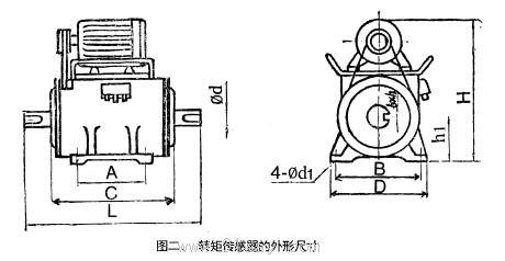
8. The external dimensions are shown in Figure 2.
9. Working hours: Can run continuously

|
A |
C |
L |
h1 |
B |
D |
H |
d1 |
|
b |
h |
d |
| ZJ-0.1,0.2 |
one hundred and ten |
two hundred |
two hundred and sixty |
ninety |
one hundred and fifty |
one hundred and eighty |
three hundred |
eleven |
one hundred and twenty |
four |
two point five |
twelve |
| ZJ-0.5,1,2 |
one hundred and ten |
two hundred |
two hundred and sixty |
ninety |
one hundred and fifty |
one hundred and eighty |
three hundred |
eleven |
one hundred and twenty |
four |
two point five |
twelve |
| ZJ-5,10,20 |
one hundred and seventy-two |
two hundred and sixty |
three hundred and seventy |
one hundred |
one hundred and eighty-two |
two hundred and ten |
three hundred and twenty |
twelve |
one hundred and twenty |
eight |
four |
twenty-six |
| ZJ-50,100,200 |
one hundred and seventy |
three hundred |
four hundred and thirty |
one hundred and ten |
two hundred |
two hundred and thirty |
three hundred and forty-five |
sixteen |
one hundred and twenty |
spline |
8-48×42×8 |
| ZJ-500,1000,2000 |
two hundred and twenty-four |
four hundred |
six hundred and sixty |
one hundred and twenty |
two hundred and thirty |
two hundred and sixty-two |
three hundred and ninety |
eighteen |
one hundred and twenty |
10-100×90×14 |
1. Sensors must be installed securely to prevent vibration during operation.
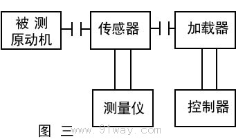
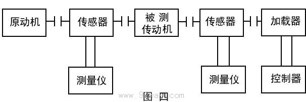
2. The installation position of the sensor is shown in Figures 3 and 4.


3. The installation concentricity of the sensor should not exceed 0.1mm, otherwise, the measurement accuracy of the instrument cannot be easily guaranteed.
4. The coupling on the load side of the sensor should be easily detachable for zero point adjustment.
5. Since the speed signal of the sensor is the algebraic sum of the shaft speed and the sensor sleeve speed, when the drive motor on the sensor is turned on
At this time, the torque shaft speed should be equal to the difference between the instrument speed reading and the sensor motor speed.
6. Sensors should strive to avoid vibration during use.
7. The change in ambient temperature will directly affect the measurement accuracy of the instrument. When the measurement accuracy requirement is not high, relative to the calibration temperature of the sensor
When the temperature difference is within ± 10 ℃, the calibration coefficient does not need to be modified. If the ambient temperature exceeds this range, the calibration coefficient of the sensor must be adjusted
The value needs to be corrected, that is, the TR-1 coefficient needs to be corrected before use, in order to ensure the accuracy of the instrument testing. The correction of the temperature coefficient is calculated according to the following formula:
Xt=Xto[1+εG(t-to)]
In the formula: Xt - Sensor coefficient at temperature t.
Xto - The sensor coefficient calibrated when the temperature is to (i.e. the temperature coefficient of the sensor on the nameplate).
T - The actual ambient temperature during measurement in ℃.
To - The ambient temperature (℃) at which the sensor coefficient is calibrated.
The temperature coefficient of the shear elastic modulus G, denoted as ε G, is taken as 0.027% here.
For example, the calibration coefficient of the sensor at the factory was 7215, which was calibrated at 10 ℃. Now it is used at 36 ℃, and its correction is necessary
The coefficient is: Xt=7215 × (1-0.027% × 26 ℃)=7164
Correct the calibration coefficient of the sensor to 7164 and set the coefficient of TR-1 to 7164 during use. If the ambient temperature is still 10 ℃, then
The coefficient remains at 7215.
8. Operation steps:
(1) Connect the sensor to the measured power transmission shaft and load block diagram in a secure manner, as well as the installation and connection of items 1-4 mentioned above.
(2) Connect the signal output line to TR-1 and set the calibration coefficient of TR-1 according to the coefficient value indicated on the sensor nameplate.
(3) Disconnect the load side coupling, start the tested machinery, adjust the zero point of TR-1. If the output voltage signal amplitude is low due to low speed
At 0.7V, the driving motor on the sensor can be activated and rotated in the opposite direction to the measuring shaft, but at this speed
Obtain according to Article 5.
(4) Once the coupling is connected, measurements can be taken.
9. Maintenance requirements:
(1) The sensor assembly undergoes careful debugging and compensation before leaving the factory, and must not be disassembled or assembled casually to avoid losing accuracy.
(2) After using the sensor for a period of time, if calibration or maintenance is required, please return it to our factory for re calibration.
(3) Sensors should be avoided from use and stored in environments with severe vibration and high temperature and humidity.
(4) The packaging and transportation of sensors should be carried out in accordance with the "Precision Instrument Packaging and Transportation Measures".

 Your location:Home → instrumentation and meters → tachometer → speed sensor → ZJ Torque and speed sensor

 Zoom in on the image

 Related Products:
 J90LWX03 Type Permanent Magnet DC Brushless T..
 Electrical instruments
  tachometer
 沪公网安备31010702003255号
