
| Product name: | FN5 series indoor AC high voltage load switch | ||||||
| specification: |  |
||||||
| Category: | High voltage electrical appliances -- Indoor high-voltage load switch | ||||||
| Price: | factory price | ||||||
| Brand: | Shanghai | ||||||
| Place of Origin: | China | ||||||
| Available Quantity: | batch | ||||||
| delivery cycle: | Spot goods (or inquire by telephone) | ||||||
|
|||||||
The FN5-12 indoor AC high-voltage load switch (hereinafter referred to as the load switch) is suitable for use in AC 50Hz, 12kV networks, as a means of breaking load currents and closing short-circuit currents. Load switches with fuses can cut off short-circuit currents and serve as protective switches.
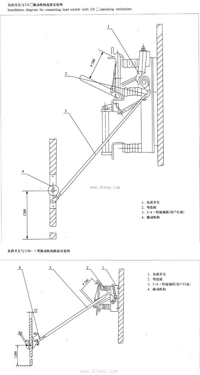
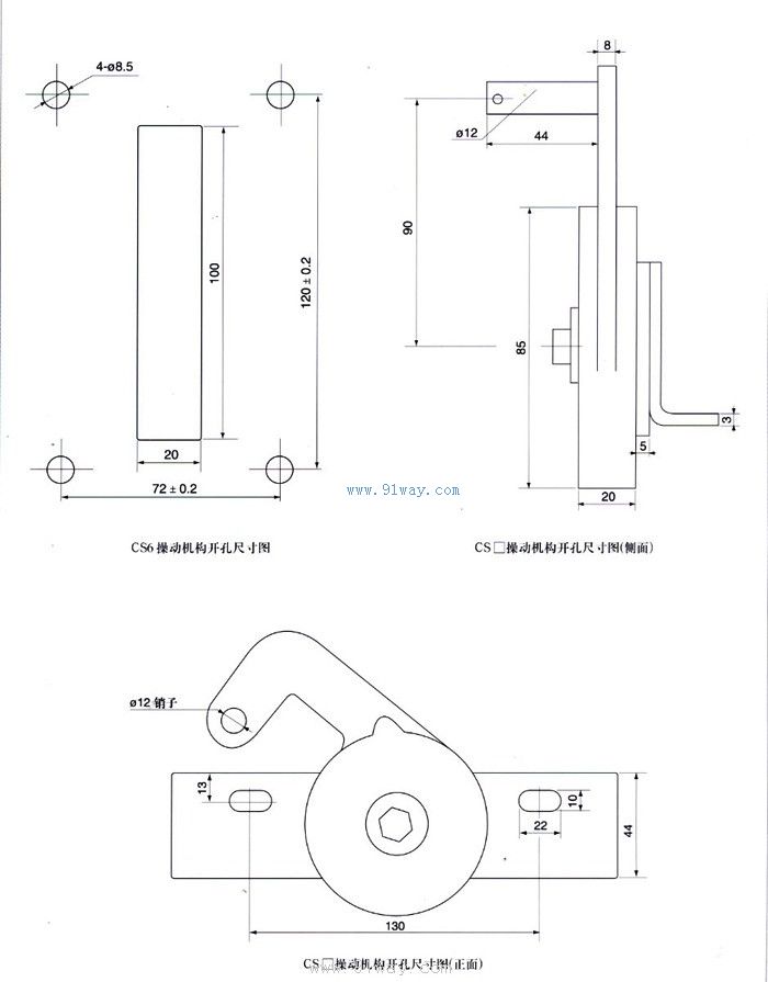
The load switch can be equipped with CS6-1 mobile phone operating mechanism, CS □ manual operating mechanism dedicated to this product, or CJ □ electric operating mechanism.
Model and its meaning
Environmental conditions for use
1. Altitude not exceeding 1000m;
2. Surrounding air temperature: upper limit+40 ℃, lower limit -25 ℃ (electric mechanism not lower than -5 ℃);
3. Relative humidity: daily average not exceeding 95%, monthly average not exceeding 90% (+25 ℃);
4. The surrounding air should not be significantly polluted by corrosive or flammable gases, water vapor, etc;
5. No frequent severe vibrations.
Main technical parameters of FN5 series indoor AC high-voltage load switch

Note: The grounding part of FN5-12D load switch also has short-circuit closing capability.
Appearance and installation dimensions
The appearance and installation dimensions of FN5-12 load switch are shown in Figure 1.
The appearance and installation dimensions of FN5-12D load switch are shown in Figure 2.
The appearance and installation dimensions of FN5-12R load switch are shown in Figure 3.
The appearance and installation dimensions of the FN5-12DR load switch are shown in Figure 4.
The appearance and installation dimensions of FN5-12R (S) load switch are shown in Figure 5.
The appearance and installation dimensions of FN5-12DR (S) load switch are shown in Figure 6.

1. Base frame 2. Post insulator 3. Support terminal block 4. Contact blade 5. Arc extinguishing tube 6. Twisted spring and torsion spring lock shaft 7. Guide plate 8. Contact terminal block
9-Pull rod 10 Rotary shaft 11 Spring energy storage mechanism 12 Operating panel
Figure 1 Outline drawing of FN5-12 load switch
1. Base frame 2. Grounding contact blade 3. Grounding switch shaft 4. Pillar insulation 5. Grounding contact seat 6. Support wiring board 7. Load switch contact blade 8. Arc extinguishing tube 9. Twisted spring and torsion spring pin shaft 10. Guide plate 11. Contact seat wiring board 12. Pull rod 13. Load switch shaft 14. Load switch spring energy storage structure 15. Grounding switch spring energy storage mechanism 16. Load switch operation panel 17. Grounding switch operation panel 18. Interlocking mechanism
Figure 2 Outline drawing of FN5-12D load switch


1-FN5-12 load switch 2-support fuse terminal block 3-pillar insulator 4-grounding contact seat
Figure 3 Outline drawing of FN5-12R load switch
1-FN5-12D load switch 2-support fuse terminal block 3-fuse tube 4-interlocking mechanism 5-fuse terminal block 6-fuse base
Figure 4 Outline drawing of FN5-12DR load switch


1-FN5-12 load switch 2-support fuse terminal block 3-fuse tube 4-fuse terminal block 5-fuse base
Figure 5 Outline drawing of FN5-12R (S) load switch
1-FN5-12D load switch 2-support fuse terminal block 3-fuse tube 4-fuse terminal block 5-fuse base 6-edge locking mechanism
Figure 6 Outline drawing of FN5-12DR (S) load switch
Ordering Instructions
When placing an order, the following items should be specified:
1. The model, name, and quantity of the load switch.
2. If equipped with a fuse, please indicate the model, rated voltage, and rated current of the fuse.
3. The model of the accompanying institution.

Home|Quality Commitment|Ordering|Payment method|product delivery|support|Disclaimer|Contact Us
Copyright®2011 www.91way.com Copyright.
Phone:+86-21-66770508 +86-13916500500 Fax:+86-21-66108310
Email:91way@163.com Wechat:40606422
沪ICP备2021005791号 ![]() 沪公网安备31010702003255号
沪公网安备31010702003255号