
 Your location:Home → Pump valve fittings → Pump products → mixed-flow pump → HFL acid resistant mixed flow pump
 |
Product name: | HFL acid resistant mixed flow pump | |||||
| specification: |   Zoom in on the image Zoom in on the image |
||||||
| Category: | Pump valve fittings -- mixed-flow pump | ||||||
| |
Price: | factory price | |||||
| Brand: | Shanghai | ||||||
| Place of Origin: | China | ||||||
| |
Available Quantity: | batch | |||||
| delivery cycle: | Spot goods (or inquire by telephone) | ||||||
 |
|
||||||
Structural characteristics of HFL acid resistant mixed flow pump
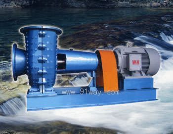
1. This pump is designed according to the required parameters of the process and the optimal flow conditions. The pump type adopts a vortex shell mixed flow pump.
2. This pump adopts a rear opening pull-out structure pump, which is easy to disassemble and maintain. During maintenance, the connecting pipeline can be removed without disassembling the pump shaft.
3. The shaft seal adopts a new combination seal, which is suitable for transporting highly corrosive liquids containing suspended particles.
4. The pump body flow channel is spacious and not easily blocked, with a large cavitation allowance. The shaft and bearing design are highly reliable to ensure smooth operation, low vibration, low noise, and long service life.
5. The direction of rotation of the pump is indicated by arrows on the bearing bracket.
The significance of HFL acid resistant mixed flow pump model

1. Front pump cover 2, pump body 3, impeller nut 4, impeller 5, rear pump cover 6, mechanical seal cover 7, mechanical seal combination
8. Shaft sleeve 9, front axle pressure cover 10, bracket 11, pump shaft 12, bearing box 13, rear axle pressure cover
Performance Parameter Table
|
Model Flow Q (m3/h) Head H (m) Speed N (r/min) Power N (KW) |
Disassembly and assembly of pumps
The disassembly sequence of the pump
1.1 Remove the cooling water pipe
1.2 Remove the middle connecting piece of the coupling, dismantle the connecting bolts between the pump body and the middle bracket, and take out the rotor component from the pump body. After removing the motor without an intermediate coupling, exit the pump shaft.
1.3 Loosen the impeller nut and remove the impeller and key.
1.4 Remove the pump cover, mechanical gland, shaft sleeve, and other sealing components.
1.5 Remove the connecting bolts between the bearing box and the intermediate bracket, and take out the intermediate bracket.
1.6 Disassemble the coupling, key, bearing cover, round nut, etc., and remove the shaft and bearing together from the bearing box towards the drive end.
1.7 Disassemble the bearings and shaft.
2. Pump assembly
The assembly sequence of the pump can be reversed in the disassembly sequence, but during assembly, attention should be paid to checking the integrity of each sealing surface gasket and the assembly clearance of related parts.
Pump installation
1. After opening the box, check that the pump and motor are not damaged, the fasteners are not loose, and there are no foreign objects in the pump inlet and outlet. They can be directly sent to the installation site for use.
2. After the precast foundation for installing the pump unit solidifies, place the base on the foundation and adjust it with shims to keep the pump and motor level. After grouting, wait for the base, anchor bolts, and foundation to be tightened, tighten the anchor bolts.
3. The pump and motor must be aligned, and the coaxiality error of the coupling should not exceed 0.1mm. The maximum difference in clearance between the end faces of the two couplings should not exceed 0.3mm.
Starting, stopping, and running of the pump
1. Start and Stop
(1) Check the oil level inside the bearing box, which should be controlled within 2mm above and below the center line of the oil level.
(2) Before connecting the pump, check if the motor direction is correct.
(3) Rotate the coupling by hand and feel that the weight is evenly distributed and there is no friction inside the pump.
(4) Check if the external cooling water pipes and flushing liquid connections are unobstructed.
(5) Start the motor and observe its operation to ensure there are no abnormal phenomena.
(6) When stopping the pump operation, first close the inlet and outlet pipeline valves, stop the motor operation, and close the washing liquid pipe valve.
2. Operation
(1) During driving and operation, it is necessary to regularly observe instrument readings, pay attention to bearing temperature rise, leakage and heating of sealing cooling water, pump vibration and noise, etc. to ensure that they are normal. If any abnormal situations are found, they should be dealt with in a timely manner.
(2) The maximum temperature of the bearing shall not exceed 80 degrees
(3) The bearing oil level should be kept at the normal position, not too high or too low, and should be replaced with new oil regularly according to usage.

 Related Products:
 VTM type vertical guide vane mixed flow pump .. TKX(S),LKX(S),LBX(S) type vertical mixed flow.. MECP type mixed flow pump SBHL type vertical core pumping mixed flow pu.. HB,HBF type mixed flow pump HWZ type direct coupled mixed flow pump SPP type chemical mixed flow pump HBC type snail shell mixed flow pump HL,HLB type mixed flow pump HW type vortex shell mixed flow pump Related articles:
 Pump products
  pump head air pump electric pump Process pump vane pump frequency conversion pump variable displacement pump manual pump pressure pump plastic pump gear pump Mid open pump mixed-flow pump
  centrifugal pump feed pump circulation pump Drainage pump rotary pump pipeline pump submersible pump axial flow pump magnetic drive pump self-priming pump fire pump vortex pump multistage pump vacuum pump chemical pump screw pump submerged pump metering pump diaphragm pump reciprocating pump plunger pump drive pump canned motor pump pressure test pump marine pump air conditioning pump civilian pump Sanitary pump Insulated pump peristaltic pump lubrication pump cooling pump jet pump fountain pump Asphalt pump Aeration machine Slag(mud)slurry pump Sewage pump Oil pump valve products actuator pipe fittings sealing element fan
 Home|Quality Commitment|Ordering|Payment method|product delivery|support|Disclaimer|Contact Us
Copyright®2011 www.91way.com Copyright.
Phone:+86-21-66770508 +86-13916500500 Fax:+86-21-66108310
Email:91way@163.com Wechat:40606422
沪ICP备2021005791号  沪公网安备31010702003255号

