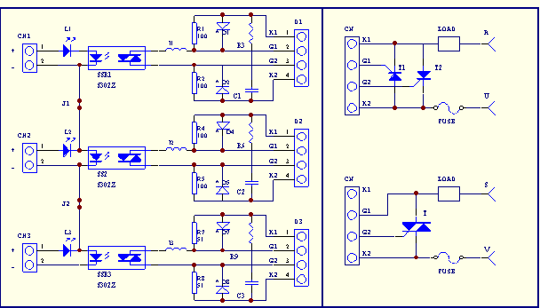
SW03A is designed with Stone small power extension solid-state relays to drive three single-phase or three-phase high-power anti parallel thyristors or bidirectional thyristors. The input level and Japanese Island Electric Duty Cycle (P-type, SSR) regulation output type instruments are compatible, such as SR90, SR70 series, etc. Its installation method is DIN standard rail or four hole screw. The input uses UL standard power connection terminals, and the output uses pluggable terminals, making it convenient for users to use. It can work under both 220V AC and 380V AC, and is equipped with S302Z expansion (non resistance capacitive circuit) solid-state relay. Figure 1 is a schematic diagram of the circuit. When the solid-state relay in the front stage is conducting, the high-power thyristor in the rear stage is forced to conduct, and there are no special requirements for the thyristor in the rear stage. Taking channel one as an example, the specific functions of the components in the circuit are as follows: I1 is the current limiting inductance of the front-end solid-state relay; R1 and R2 are cathodic resistances used to increase static dv/dt; C1 and R3 are resistance capacitance absorption circuits; L1 is the input indicator LED; Each solid-state relay requires an input of no less than 5V and a driving current of no less than 15mA (maximum not exceeding 30mA). The factory operates in a three-phase mode with J1 and J2 short circuits, and only the L1 LED is retained as the input indicator. J1 and J2 open circuits form three independent single-phase circuits. Terminals D1-D3 can be wired according to the circuit schematic. In addition, when driving two unidirectional thyristors, two reverse protection diodes D1-D8 (1N4007) can be installed. The internal resistance capacitance absorption element is 180 Ω and 0.1UF, and can also be equipped with an external resistance capacitance suction device according to the actual load situation. Common faults and troubleshooting: A: There is a situation where, due to the high-power thyristors (especially dual silicon) in the rear stage, when the small solid-state relay conducts, the thyristors in the rear stage fail to conduct in time, causing excessive current in the front stage and burning out the current limiting inductor or solid-state relay in the front stage. B: When the thyristor of the rear stage is not connected, a 12V voltage is input, and the quality of the front stage solid-state relay can be measured using a pointer multimeter in the resistance range. C: User experience with domestically produced bidirectional thyristors (reference): It is recommended to use 2-3 phase limit, which means negative pulse triggering.
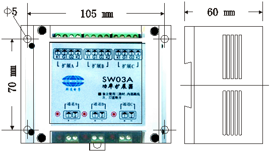
Installation dimensions of SW03A three circuit thyristor power expander

SW03A schematic diagram

A) Directly connect SSR output type instrument (omitted)
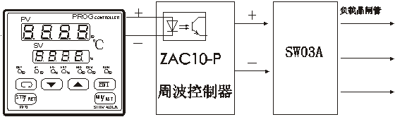
B) Application example of power extension with frequency band

enclosure. Introduction to Zero Crossing Cycle: The most widely used SSR signal processing controller in industrial electric heating systems, it can accept PWM or 4-20mA input, generate two types of outputs: cycle zero crossing (PWM duty cycle control) and cycle zero crossing (CYC variable cycle), and directly drive the Himanton SSR power expansion board. It has hard manual operation and auxiliary power adjustment functions, advanced zero crossing frequency output, and due to the uniform distribution of load current in sine waves, the randomness and superposition of multiple equipment operation, the total power load current is relatively balanced. It improves the adjustment accuracy and power utilization efficiency, and avoids meter needles and power equipment capacity expansion, resulting in significant energy-saving effects.

 Your location:Home → Electronic and Electrical Appliances → Power Electronics → thyristor → SW03A Three circuit thyristor power expander

 Zoom in on the image

 Related Products:
 Parke DC thyristor speed controller
  沪公网安备31010702003255号




