
 |
Product name: | F-1 type flow switch | |||||
| specification: |   Zoom in on the image Zoom in on the image |
||||||
| Category: | instrumentation and meters -- flow switch | ||||||
| |
Price: | factory price | |||||
| Brand: | Shanghai | ||||||
| Place of Origin: | China | ||||||
| |
Available Quantity: | batch | |||||
| delivery cycle: | Spot goods (or inquire by telephone) | ||||||
 |
|
||||||
|
model
Model |
Piping size connecting size
(inch) |
Flow regulation range during switch action
Flow range (Liter / min) | |||
|
Minimum adjustment |
Maximum adjustment | ||||
|
Decreased traffic
Flow decreasing |
Traffic increase
Flow increasing |
Decreased traffic
Flow decreasing |
Traffic increase
Flow increasing | ||
|
F-1 |
one |
eighteen |
twenty-one |
forty-five |
fifty |
|
1-1/2 |
thirty |
thirty-five |
one hundred |
one hundred and five | |
|
two |
fifty |
fifty-eight |
one hundred and fifty |
one hundred and fifty-five | |
|
2-1/2 |
seventy-five |
eighty-six |
one hundred and eighty-seven |
two hundred | |
|
three |
one hundred |
one hundred and fifteen |
two hundred and twenty-five |
two hundred and sixty | |
|
four |
one hundred and ten |
one hundred and fifty-four |
three hundred and seventeen |
three hundred and thirty-seven | |
|
five |
one hundred and seventy |
two hundred and thirty-six |
four hundred and sixty-two |
four hundred and ninety | |
|
six |
two hundred and twenty-five |
three hundred and eight |
five hundred and sixty-two |
five hundred and ninety-nine | |
|
eight |
seven hundred and seven |
eight hundred and fifty-four |
one thousand six hundred and sixty-four |
one thousand seven hundred and twenty-seven | |
|
Rated Voltage
supply voltage(V)
rated current
operating current (A) |
Power Supply
COSф |
125V
AC |
250V
AC | |
|
Non induction current (A) |
one |
fifteen |
fifteen | |
|
Induction current (A) |
Constant current |
zero point seven five |
three point five |
two point five |
|
Instantaneous current transient |
zero point seven five |
twenty-one |
fifteen | |
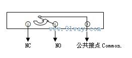
|
Phenomena and Problems
Trouble |
Elimination methods
Solution |
|
Damaged corrugated pipe with liquid leakage
Bellows is damaged, liquid is leaking |
exchange
Replacement |
|
The mechanical part is stuck by debris and the switch does not operate
Mechanism is locked by scraps, switch fails to act |
Remove debris
Wipe out the scraps |
|
Reverse or no action of control switch
Switch reverse action or no action |
Check the wiring and whether the contacts are reversed
View on wiring to see if exists wrong wiring |
|
The control switch operates when there is liquid flow, but cannot reset when there is no liquid flow |
Ensure liquid upwards and arrow on enclosure upwards on the vertical line on the vertical pipeline, with the arrows pointing upwards towards the outer shell |
|
The switch does not operate when the traffic increases
When flow increasing, switch does not act |
Check if there are cracks or fractures in the flow direction sheet, |
|
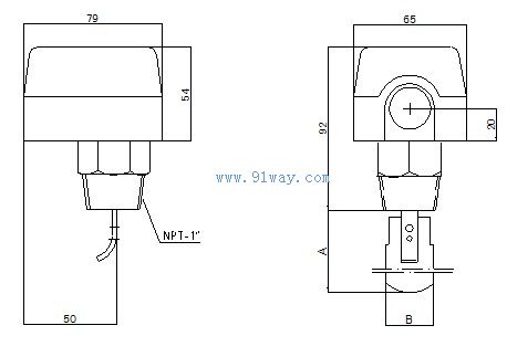
Paddle NO. |
A (mm) |
B(mm) |
|
one |
thirty-five |
twenty-seven |
|
two |
sixty |
twenty-seven |
|
three |
eighty-eight |
twenty-seven |
|
four |
one hundred and twenty-one |
twenty-seven |
|
five |
one hundred and fifty |
twenty-seven |
Ordering Instructions
When leaving the factory, connect according to the form, size, and small flow rate setting value shown in the diagram Delivery
The flow rate in the technical parameters is provided as a reference for selection.
If there are any other special requirements such as takeover form and size, please raise them when ordering

 Related Products: Related articles:
 Electrical instruments Digital Display Instrument Temperature Instrument Humidity meter Pressure gauge flow meter
  current meter flow switch
  V-Cone flowmeter oval gear flow meter float flow meter Scraper flowmeter orifice plate flowmeter Gas flowmeter mass flow meter Pipeline flowmeter Electromagnetic Flowmeter steam flow meter Gear flow meter rotameter turbine flow meter vortex flow meter Open channel flowmeter Other flow meters ultrasonic flowmeter flow sensor Flow Transmitter flow controller Flow integrator analytical instrument Level instrument tachometer Recording instrument weighing instrument Specialized instruments
 Home|Quality Commitment|Ordering|Payment method|product delivery|support|Disclaimer|Contact Us
Copyright®2011 www.91way.com Copyright.
Phone:+86-21-66770508 +86-13916500500 Fax:+86-21-66108310
Email:91way@163.com Wechat:40606422
沪ICP备2021005791号  沪公网安备31010702003255号
 Your location:

