
 Your location:Home → instrumentation and meters → Level instrument → level switch → DF-96B Fully automatic liquid level controller for water pump
 |
Product name: | DF-96B Fully automatic liquid level controller for water pump | |||||
| specification: |   Zoom in on the image Zoom in on the image |
||||||
| Category: | instrumentation and meters -- level switch | ||||||
| |
Price: | factory price | |||||
| Brand: | Shanghai | ||||||
| Place of Origin: | China | ||||||
| |
Available Quantity: | batch | |||||
| delivery cycle: | Spot goods (or inquire by telephone) | ||||||
 |
|
||||||
Installation of DF-96B Automatic Liquid Level Controller for Water Pump
(1) Installation instructions for the single control upper water tank control head. The installation diagram is shown in Figure 1:
A (meridian) - is the upper limit liquid level control point of the upper water tank (water tower). When the water level rises to point A, the water comes into contact with the probe, and the water controller automatically shuts off the pump;
B (blue line) - is the lower limit liquid level control point of the upper water tank (water tower). When the water level drops below the water level at point B, the water and probe are out of contact, and the water level controller automatically starts the pump, filling the water tank with water;
C (black line) - is the ground wire of the water tank (water tower), placed at the lowest point of the water tank and in contact with the bottom of the water tank;
Connect point D (green line) and point E (yellow line) to point C.
(2) Installation instructions for the probe of the single control lower water tank (i.e. drainage tank): The installation diagram is shown in Figure 2:
E - is the upper limit liquid level control point of the lower water tank. When the water rises to the water level at point E and comes into contact with the probe, the water level controller automatically starts the pump and the water tank drains; If there is no drainage, point E will not be connected;
D - is the lower limit liquid level control point of the lower water tank. When the water level drops to point D, the water and the control head are out of contact, and the water level controller automatically shuts off the pump, stopping the drainage of the water tank;
C - is the ground wire of the water tank, and the lowest point of the water tank is in contact with the bottom of the water;
A. Point B is not connected.
(3) Installation instructions for water shortage protection probe: The installation diagram is shown in Figure 3:
C. Point D is the lower limit water level control point of the pool. When the water level drops to the lower limit water level, one of the C and D probes disengages from the water surface, and the water level controller relay immediately acts to cut off the output, and the water pump stops working;
Short circuit between point E and point C;
A. Point B is not connected.
Click count: 3482 Upload time: August 23, 2007
(4) Installation instructions for the joint control probe of the upper and lower water tanks. The installation diagram is shown in Figure 3:
A - is the upper limit liquid level control point of the upper water tank (water tower). When the water level rises to point A, the water comes into contact with the control head, and the water controller automatically shuts off the pump;
B - is the lower limit liquid control point of the upper water tank (water tower). When the water level drops below point B, the water and probe are out of contact, and the water level control automatically starts the pump, filling the water tank with water;
C - It is a shared online connection for the upper and lower water tanks (water towers), placed at the lowest point of the upper and lower water tanks in contact with the bottom of the tank;
D - is the lower limit liquid level control point of the lower water tank. When the water level drops to point D, the water and probe are out of contact, and the water level controller automatically shuts off the pump, the water tank stops draining;
E - is the upper limit liquid level control point of the lower water tank. When the water level rises to point E, the water comes into contact with the probe, and the water level controller automatically starts the pump and the water tank head; If there is no drainage, point E will not be connected.
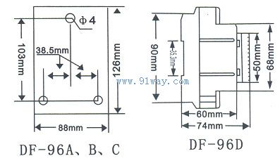
installation dimensions
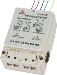
DF-96B water pump automatic liquid level controller
 Related Products:
 RF-9000/9200 series capacitor level controlle.. RF-9300 type RF admittance level controller UDK-900 Type Electric Contact Liquid Level Co.. URD Thermal conductive level controller UZK Resistance rotary level controller UZG-01 Vibration rod type material level cont.. UTK Float level controller UHZ-58/S-UK series plug-in magnetic liquid le.. DF-96A Water level controller JY-1GF High temperature anti-corrosion liquid.. Related articles:
 Electrical instruments Digital Display Instrument Temperature Instrument Humidity meter Pressure gauge flow meter analytical instrument Level instrument
  float ball Collimator Inclinometer Length measuring instrument linear scale level meter level gauge Hall switch Magnetic switch photoelectric switch proximity switch level switch
  Level switch Level transmitter Level controller level sensor Level transmitter level controller angle sensor displacement sensor Displacement transmitter vibration sensor tachometer Recording instrument weighing instrument Specialized instruments
 Home|Quality Commitment|Ordering|Payment method|product delivery|support|Disclaimer|Contact Us
Copyright®2011 www.91way.com Copyright.
Phone:+86-21-66770508 +86-13916500500 Fax:+86-21-66108310
Email:91way@163.com Wechat:40606422
沪ICP备2021005791号  沪公网安备31010702003255号

