|
Product name: |
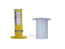
QBJ-3XN Fuel tank oil level monitoring and protection device
|
|
specification: |
|

 Zoom in on the image Zoom in on the image |
|
Category: |
instrumentation and meters
-- Engineering instruments |
|
Price: |
factory price |
|
Brand: |
Shanghai |
|
Place of Origin: |
China |
|
Available Quantity: |
batch |
|
delivery cycle: |
Spot goods (or inquire by telephone) |
|
| |
Shanghai Beiyuan Industry and Trade Co.,Ltd
+86-21-66770508
+86-13901609058 |
 91way@163.com 91way@163.com
 13901609058(Wechat) 13901609058(Wechat)
|
|
|
|
QBJ-3XN Fuel tank oil level monitoring and protection deviceDetailed product description:

The QBJ-3XN type hydraulic servo motor monitoring and protection device is equipped with TD-1 type sensor to achieve measurement of the hydraulic servo motor. Oil motor monitoring is used to measure the opening degree of the turbine oil motor, which is important for the normal operation of the entire unit. Use UT-81A sensor to measure the oil level in the fuel tank.
Technical specifications of QBJ-3XN fuel tank oil level monitoring and protection instrument
Measurement range: 0-200mm (range can be customized by the user)
0 to ± 200mm (range can be customized by the user)
Accuracy: System error ≤ 1%
Usage environment: Instrument temperature: -10 ℃~45 ℃
Relative humidity ≤ 80% (instrument)
Sensor temperature: -25 ℃~85 ℃
Relative humidity ≤ 90% (sensor)
Constant current output: 4-20mA
Alarm setting: set arbitrarily within the measurement range
Power supply: AC 220V ± 10% 50Hz
Dimensions: 160 × 80 × 260mm (depth)
Hole size: 154 × 78 × 260mm (depth)
Working principle of QBJ-3XN fuel tank oil level monitoring and protection instrument
The working principle of this monitoring device can be seen from the block diagram, which consists of an oscillation circuit, a constant current source, a discriminator, etc. The internal iron core of the displacement sensor is wound with two sets of coils, which move inside the sensor housing. When a certain frequency of AC voltage is applied to the coils, an electrical signal corresponding to the displacement of the iron core is generated. The oscillator generates an oscillating voltage of 1-3KHz, which enters the signal processing stage. When the sensor is turned on, the 1-3KHz AC power enters the sensor. As the displacement of the sensor core changes, it is transformed by the signal processing stage to obtain a 0-5V voltage proportional to the position of the core. This voltage is output through a buffer to produce a 0-5V voltage signal, another through V/I conversion to produce a 4-20mA current output, and another through an alarm circuit for identification. When it exceeds the limit, an alarm signal can be issued.
Main functions
Travel displacement display, alarm (positive, negative) respectively, (positive, negative) dangerous relay contact output ● Range lower limit to upper limit: Current corresponds to (4-20mA) output respectively
Power on reset delay, normal light off, when restored, lock delay of 5 seconds is released
The alarm danger value can be set arbitrarily (within the range)
Alarm hazard relay output delay four level setting value selection
Free range setting
In the data setting value view, if no keyboard operation is performed for 1 minute, it will automatically return to the measurement state
Installation method
1. The TD-1 type hydraulic engine stroke sensor can be installed at any position, with installation dimensions as shown in the figure. However, it should be at least the height of the installation bracket away from the magnet or metal object, and the sensor housing should not be close to strong magnetic fields and high current wires.
2. The installation of the sensor's armature requires linear movement and repeated movement several times after completion to avoid jamming. It is best to use shielded wires for the signal lines of sensors to avoid signal interference. The rest are used with reference to the thermal expansion detection device.
3. When wiring sensors, they are generally connected to the instrument input terminals by pressing 1, 2, and 3 respectively. To change the measurement direction, they can be connected to the input terminals by pressing 3, 2, and 1.
4. When the instrument output is used in conjunction with the computer DCS system, its output 4-20mA current line cannot be connected in series with other lines and should be independently input into the computer DCS system. Constant current load ≤ 1K Ω.
5. The instruments should be installed in the control cabinet or in the local instrument cabinet.
 Related Products:
- Related articles:

 Your location:Home → instrumentation and meters → Specialized instruments → Engineering instruments → QBJ-3XN Fuel tank oil level monitoring and protection device
 WZ-7a Reverse speed detection monitoring and ..
 Electrical instruments
  Vibration meter
 沪公网安备31010702003255号