
 Your location:Home → instrumentation and meters → Pressure gauge → Pressure transmitter → SPB103 series plane membrane structure pressure transmitter
 |
Product name: | SPB103 series plane membrane structure pressure transmitter | |||||
| specification: |   Zoom in on the image Zoom in on the image |
||||||
| Category: | instrumentation and meters -- Pressure transmitter | ||||||
| |
Price: | factory price | |||||
| Brand: | Shanghai | ||||||
| Place of Origin: | China | ||||||
| |
Available Quantity: | batch | |||||
| delivery cycle: | Spot goods (or inquire by telephone) | ||||||
 |
|
||||||
SPB series plane membrane pressure transmitter uses plane membrane to directly sense pressure. The sensor interface is available in clamp type, M27 × 2, and flange type for selection. The output signals are available in voltage, current, frequency signals, etc. The flat diaphragm of the sensor prevents problems such as dirt, unhygienic, and viscous liquid blockage. Widely used in sectors such as food, medicine, health, and brewing industry
2 Technical indexes of SPB103 series plane membrane structure pressure transmitter
⑴ Power supply: 24VDC
⑵ 4-20mA non-polar connection
⑶ Working temperature: 0 ℃~100 ℃;
The accuracy level of the transmitter is divided into:
0.1 level, with a basic error of ± 0.1;
0.25 level, with a basic error of ± 0.25;
Level 0.5, with a basic error of ± 0.5 (expressed as a percentage of the measurement range).
⑸ Thermal zero drift
When the ambient temperature deviates from the reference working conditions, the zero drift of the transmitter should not exceed 0.03% FS/℃.
⑹ Thermal sensitivity drift
When the ambient temperature deviates from the reference working conditions, the full-scale drift of the transmitter should not exceed 0.03% FS/℃.
⑺ Insulation resistance
Under reference working conditions, the insulation resistance between each terminal of the transmitter and ground shall not be less than 20M Ω/250V.
⑻ Protection level: IP65
3 Electrical Connections
3.1 The electrical connections of the Hirschman structure are shown in Figures a and b below:
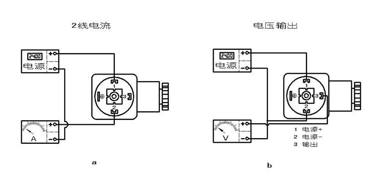
Figure 3
3.2 Direct lead structure electrical connection:
Current: Red line: 24VDC;
Green line: Current output.
Voltage: Red line: 9VDC;
Blue line: Power supply -;
Yellow line: Voltage output+.
4 Installation methods
⑴ Choose a place that is easy to operate and maintain for installation;
⑵ It should be installed as far away from the vibration source as possible;
⑶ Keep as far away from heat sources as possible;
It is best to connect the valve to the measuring pipeline;
During installation, use a wrench to clamp the six corners of the transmitter;
During operation, the connection between the Hirschmann joint and the housing cannot rotate.
5 Safety precautions for use
(1) When handling and installing transmitters, care should be taken to avoid collisions that may affect the performance of the circuit.
⑵ Do not touch the sensor diaphragm with foreign objects.
The installation site of the transmitter must be sealed carefully, otherwise it may cause inaccurate and unstable pressure.
If you encounter any problems during the installation and use of the product, please contact our company. In case of any abnormalities in the product, please do not open it for repair without authorization, and contact the manufacturer in a timely manner.

 Related Products:
 SBP800 Pressure transmitter 21PY series pocket sized pressure transmitter.. ALQ series atmospheric pressure transmitter AL-K Sanitary pressure transmitter AL High temperature pressure transmitter AL-PO Lightning protection pressure transmitt.. AL-KO-P series protective pressure transmitte.. BP500 type pressure transmitter 3651/1151 Remote pressure transmitter 3651/1151GP Capacitive pressure transmitter Related articles:
 Electrical instruments Digital Display Instrument Temperature Instrument Humidity meter Pressure gauge
  Micro pressure gauge pressure gauge Diff pressure gauge tensiometer pressure reducer pressure switch Diff pressure switch Tension controller tension sensor pressure sensor Pressure transmitter
  pressure controller Diff pressure transmitter Diff pressure controller flow meter analytical instrument Level instrument tachometer Recording instrument weighing instrument Specialized instruments
 Home|Quality Commitment|Ordering|Payment method|product delivery|support|Disclaimer|Contact Us
Copyright®2011 www.91way.com Copyright.
Phone:+86-21-66770508 +86-13916500500 Fax:+86-21-66108310
Email:91way@163.com Wechat:40606422
沪ICP备2021005791号  沪公网安备31010702003255号

