
 Your location:Home → instrumentation and meters → flow meter → vortex flow meter → LUGB-21 series intelligent vortex flowmeter
 |
Product name: | LUGB-21 series intelligent vortex flowmeter | |||||
| specification: |   Zoom in on the image Zoom in on the image |
||||||
| Category: | instrumentation and meters -- vortex flow meter | ||||||
| |
Price: | factory price | |||||
| Brand: | Shanghai | ||||||
| Place of Origin: | China | ||||||
| |
Available Quantity: | batch | |||||
| delivery cycle: | Spot goods (or inquire by telephone) | ||||||
 |
|
||||||
1、 Overview:
The LUGB-21 series intelligent vortex flowmeter is a new type of flowmeter developed based on the principle of liquid vibration, widely used in the measurement of fluids in industries such as petroleum, chemical, metallurgy, and papermaking. This flowmeter has no movable parts, strong reliability, high accuracy, and long service life, and can accurately measure the instantaneous flow rate and cumulative flow rate of liquids over a wide flow range. It is not affected by the temperature, pressure, viscosity, and composition of the medium, and is not blocked, stuck, easy to scale, resistant to high temperature and high pressure, safe and explosion-proof, suitable for harsh environments. Integrated display and remote transmission of flow scoring, and can output pulse signals or current signals to be networked with a microcomputer.
2、 Main features:
1. The structure is simple and sturdy, with no movable parts, high reliability, and very reliable for long-term operation.
2. Easy installation and convenient maintenance.
3. The detection sensor does not directly contact the measured medium, with stable performance and long lifespan.
4. The output is a pulse signal proportional to the flow rate, with no zero drift and high accuracy.
5. Wide measurement range, with a range ratio of up to 1:10.
6. Less pressure loss, lower operating costs, and more energy-saving significance.
7. Within a certain Reynolds number range, the output signal frequency is not affected by the physical properties and composition changes of the fluid. The instrument coefficient is only related to the shape and size of the vortex generator, and there is no need to compensate when measuring the fluid volume flow rate. After replacing accessories, there is generally no need to recalibrate the instrument coefficient.
8. It has a wide range of applications and can measure the flow rates of steam, liquid, and gas.
3、 Working principle:
The vortex flow sensor measures flow based on the theories of Kaman and Strouhsl regarding the generation of vortices and the relationship between vortices and flow velocity. When the medium flows through a triangular cylinder at a certain speed, an alternating arrangement of vortex bands is generated behind both sides of the triangular cylinder, known as the "Karman vortex street" (see figure below).
Due to the alternating generation of vortices on both sides of the vortex generator, pressure pulsations are generated on both sides of the generator, resulting in alternating pressure on the detection body. The piezoelectric crystal element encapsulated in the probe generates an alternating charge signal with the same frequency as the vortex under the action of alternating stress. The amplifier amplifies, filters, shapes, and finally outputs a pulse signal (or converts it into a 4-20mA signal) with a frequency proportional to the medium flow rate, which is sent to the integrator for processing, display, and control.
Within a certain Reynolds number range (2 × 10⁴~7 × 10⁶), the relationship between the release frequency f of the vortex and the fluid velocity V, as well as the width d of the upstream face of the vortex generator, is expressed as f=St · v/d. In the equation, St is the Strouhal number, which is a dimensionless coefficient. As long as the frequency f is accurately measured, the fluid velocity v can be obtained, and the volumetric flow rate can be calculated from v.
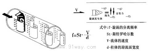
Schematic diagram of vortex generation in vortex flow sensor
4、 Technical indicators:
1. Measurement media: liquid, gas, saturated vapor, superheated vapor.
2. Accuracy level: ± 1.0% for liquids, ± 1.5% for gases (vapors), and ± 2.5% for insertions.
3. Working pressure: 1.6MPa, 2.5MPa, 4.0MPa, 6.4MPa.
4. Medium temperature: Ordinary type -40~150 ℃ Medium temperature type -40~250 ℃ High temperature type -40~350 ℃.
5. Output signal: Three wire voltage pulse, low level 0-1V, high level>4V, duty cycle 50%; The standard current for two-wire system is 4-20mA; the standard current for two-wire system is 0-10mA.
6. Working environment: -35 ℃ to+60 ℃, humidity ≤ 95% RH.
7. Working power supply: DC12V; DC24V。
8. Shell material: carbon steel, stainless steel.
9. Explosion proof type: intrinsic safety ExibIICT6.
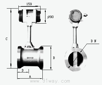
5、 External dimensions:
|
DN |
A | B | C | D |
| fifteen | ninety | Φ57 | three hundred and eighty-three | forty-five |
| twenty | one hundred | Φ57 | three hundred and eighty-eight | fifty |
| twenty-five | one hundred | Φ57 | three hundred and ninety-four | fifty |
| thirty-two | one hundred | Φ65 | three hundred and ninety-six | fifty |
| forty | one hundred | Φ75 | four hundred and one | fifty |
| fifty | one hundred and ten | Φ87 | four hundred and seven | fifty-five |
| sixty-five | one hundred and ten | Φ109 | four hundred and eighteen | fifty-five |
| eighty | one hundred and ten | Φ120 | four hundred and twenty-three | fifty-five |
| one hundred | one hundred and twenty | Φ149 | four hundred and forty-seven | sixty |
| one hundred and twenty-five | one hundred and twenty-five | Φ175 | four hundred and seventy-four | sixty-five |
| one hundred and fifty | one hundred and forty-five | Φ203 | five hundred and one | seventy-five |
| two hundred | one hundred and seventy | Φ259 | five hundred and fifty-six | one hundred |
| two hundred and fifty | one hundred and ninety | Φ312 | six hundred and eight | one hundred and twenty |
| three hundred | two hundred and ten | Φ363 | six hundred and sixty | one hundred and forty |
| three hundred and fifty | two hundred and thirty | Φ409 | seven hundred and nine | one hundred and sixty |
| four hundred | two hundred and fifty | Φ460 | seven hundred and fifty-six | one hundred and eighty |
| four hundred and fifty | two hundred and seventy-five | Φ520 | eight hundred and fourteen | two hundred and five |
| five hundred | two hundred and ninety | Φ575 | eight hundred and sixty-nine | two hundred and twenty-five |
Flow measurement range of vortex flowmeter
|
Diameter DNmm |
Gas measurement range m3/h | Liquid measurement range m3/h |
| fifteen | 0-30 | 0-8 |
| twenty-five | 8-60 | 1-12 |
| thirty-two | 12-100 | 1.5-20 |
| forty | 18-180 | 2.5-30 |
| fifty | 30-300 | 3-50 |
| sixty-five | 50-500 | 6-80 |
| eighty | 70-700 | 10-125 |
| one hundred | 100-1000 | 15-200 |
| one hundred and twenty-five | 150-1500 | 25-310 |
| one hundred and fifty | 200-2000 | 40-445 |
| two hundred | 400-4000 | 90-900 |
| two hundred and fifty | 600-6000 | 150-1500 |
| three hundred | 1000-10000 | 200-2000 |
6、 Plug in vortex flowmeter
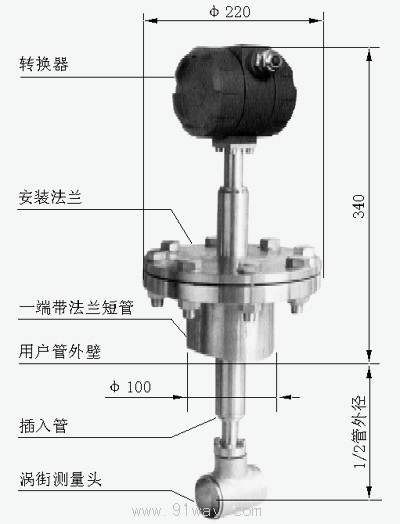
Insert the vortex street measuring head into a specific position in the pipeline, measure the local flow rate at that location, and calculate the average flow velocity value inside the pipeline based on the velocity distribution relationship of the pipeline section. It consists of a converter, an insertion rod assembly, a ball valve (as required), an installation short tube (ф 100), a vortex street measuring head, etc.
Installation steps:
1. Cut a hole slightly smaller than ф 100 and remove burrs directly above the pipeline where the flowmeter needs to be installed (this requirement applies to horizontal pipelines);
2. Place the short pipe with a flange on top of the hole, keep it perpendicular to the pipeline, and weld it firmly;
3. Place the gasket, insert the flowmeter, and connect the flange. If there is a ball valve at this time, first place the ball valve on the short pipe and connect it, then open the ball valve and insert the flowmeter;
4. Ensure that there is a straight pipe section with a diameter greater than 15D in front of the flowmeter and 5D behind it (D is the inner diameter of the pipeline).
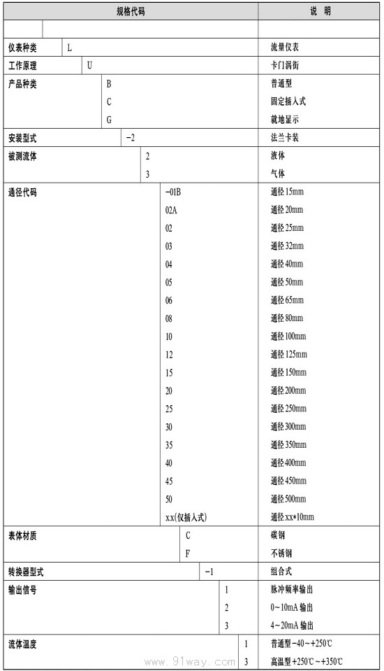
6、 Model selection
The selection of flow meters is a very important task in instrument applications. According to relevant departments, 2/3 of the failures of flow meters in practical applications are caused by incorrect selection and installation. Please pay special attention.
Requirements for straight pipe sections
In order to ensure the normal and accurate operation of the instrument, there must be a certain straight pipeline upstream and downstream of the sensor installation point to adjust the flow field, as shown in the figure.
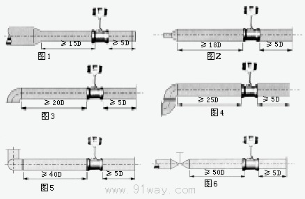
Figure 1: Concentric contraction tube;
Figure 2: Concentric expansion tube;
Figure 3: A 90 degree elbow;
Figure 4: Two 90 degree elbows on the same plane;
Figure 5: Two 90 degree elbows in different planes;
Figure 6: The regulating valve should be installed 5D downstream of the sensor. If it must be installed upstream of the sensor, there should be an equal diameter straight pipe section of not less than 50D upstream and an equal diameter straight pipe section of not less than 5D downstream.
Requirements for pipelines
1) The inner diameter D of the upstream and downstream piping is the same as the inner diameter DN of the sensor, and the difference satisfies the following condition: 0.95DN ≤ D ≤ 1.1DN.
2) The piping should be concentric with the sensor, and the coaxiality should be less than 0.05DN.
3) The sealing gasket cannot protrude into the pipeline, and its inner diameter may be slightly larger than that of the sensor.
4) If it is necessary to check and clean the sensor for flow interruption, a bypass pipeline should be installed as shown in the following figure.

 Related Products:
 TUF-2000P Portable Ultrasonic Flow Meter HS-2 type flow meter FLOW-3L Portable Doppler Flow Meter F450N, F451N series variable area flow meters.. SPX series online low flow meter KVAF Intelligent Metal Tube Float Flow Meter .. GVA type pull rod flow meter YYW Differential Vortex Flow Meter LHS-200 Spiral Flow Meter TUF-2000F Fixed Ultrasonic Flow Meter Related articles:
 Electrical instruments Digital Display Instrument Temperature Instrument Humidity meter Pressure gauge flow meter
  current meter flow switch V-Cone flowmeter oval gear flow meter float flow meter Scraper flowmeter orifice plate flowmeter Gas flowmeter mass flow meter Pipeline flowmeter Electromagnetic Flowmeter steam flow meter Gear flow meter rotameter turbine flow meter vortex flow meter
  Open channel flowmeter Other flow meters ultrasonic flowmeter flow sensor Flow Transmitter flow controller Flow integrator analytical instrument Level instrument tachometer Recording instrument weighing instrument Specialized instruments
 Home|Quality Commitment|Ordering|Payment method|product delivery|support|Disclaimer|Contact Us
Copyright®2011 www.91way.com Copyright.
Phone:+86-21-66770508 +86-13916500500 Fax:+86-21-66108310
Email:91way@163.com Wechat:40606422
沪ICP备2021005791号  沪公网安备31010702003255号

