
 Your location:Home → Pump valve fittings → valve products → electric valve → VA7010 series switch type electric valve
 |
Product name: | VA7010 series switch type electric valve | |||||
| specification: |   Zoom in on the image Zoom in on the image |
||||||
| Category: | Pump valve fittings -- electric valve | ||||||
| |
Price: | factory price | |||||
| Brand: | Shanghai | ||||||
| Place of Origin: | China | ||||||
| |
Available Quantity: | batch | |||||
| delivery cycle: | Spot goods (or inquire by telephone) | ||||||
 |
|
||||||
The VA7010 series switch type electric valve consists of a VAA7010 series valve driver and a VAV7010 series copper valve. Used to control the opening or closing of pipelines in cold or hot water air conditioning systems, achieving the goal of controlling room temperature. The driver is driven by a unidirectional hysteresis synchronous motor, and the valve spring is reset. When the valve is not working, it is in a normally closed state. When it needs to work, the temperature controller provides an opening signal to connect the electric valve to the AC power supply and activate it. When the valve is opened, chilled water or hot water enters the fan coil unit to provide air conditioning or heating for the room; When the room temperature reaches the set value of the thermostat, the thermostat cuts off the power to the electric valve, and the reset spring closes the valve, thereby cutting off the water flow into the fan coil. Keep the room temperature within the temperature range set by the thermostat by closing or opening the valve.
The driver and valve body of the VA7010 series electric valve are connected by a screw sleeve. The driver can be installed after the valve is installed and assembled on site, with flexible and convenient wiring.
The planar design of the driver can be installed close to the wall, occupying less space. The product is reliable and durable, with low working noise, and can work reliably in high-temperature environments commonly found in concealed fan coil units.
Main technical parameters of the driver
| Model | Rated Voltage | power | Drive Type | Coordinated action time with SRV2000 valve | Net Weight (kg) |
| VA7010-220 |
AC220V±10% |
7W | Unidirectional motor drive Valve spring reset |
Full open time: about 10 seconds after power on Shutdown time: About 5 seconds after power failure |
zero point three |
| Product Model | valve type | connection thread | flow coefficient Kv |
Close the pressure differential (MPa) |
work medium |
fluid temperature |
environment temperature |
Storage temperature |
under pressure (MPa) |
| VA7010-15 | Normally closed two-way valve | G1/2 | one point five | zero point two five | Freezing/ hot water |
2-94℃ | 0-60℃ Maximum relative The humidity is not dew |
-20-65℃ Maximum relative The humidity is not dew |
one point six |
| VA7010-15 | Mixed three-way valve | G1/2 | one point five | zero point two five | |||||
| VA7010-20 | Normally closed two-way valve | G3/4 | two point five | zero point one | |||||
| VA7010-20 | Mixed three-way valve | G3/4 | two point five | zero point one | |||||
| VA7010-25 | Normally closed two-way valve | G1 | four point eight | zero point zero six | |||||
| VA7010-25 | Mixed three-way valve | G1 | four point eight | zero point zero six |

| Model | Size (mm) | Net weight (kg) | |
| A | B | ||
| VA7010-15 | fifty-five | one hundred and thirteen | zero point six zero |
| VA7010-15 | fifty-five | one hundred and twenty-eight | zero point six zero |
| VA7010-20 | sixty-six | one hundred and twenty-four | zero point six five |
| VA7010-20 | sixty-six | one hundred and thirty-seven | zero point six five |
| VA7010-25 | ninety | one hundred and twenty-nine | zero point seven zero |
| VA7010-25 | ninety | one hundred and forty-five | zero point seven zero |
Material Description
Valve body material: forged brass
Sealing material: Nitrile rubber (NBR)
Driver cover: flame retardant ABS engineering plastic
Medium temperature: < 94 ℃
Valve stem material: stainless steel (A1S162)
Drive chassis: die cast aluminum alloy
Working medium: water
Operation and precautions
The motor casing prevents water from seeping in. When the valve is installed in a horizontal pipeline, the installation position should not exceed an angle of 85 ° with the vertical plane, as shown in Figure 2. When the valve is installed on a vertical pipeline, the motor casing must prevent dripping water from seeping in.
When moving the manual control lever, it should be moved slowly. When the manual lever moves slowly in the direction of the arrow and clicks into the notch, the valve is in a normally open state. Whenever the current first passes through the electric valve, the manual lever will be set to the automatic position again.
Installation instructions
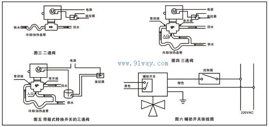
The installation of normally closed two-way valves and mixed three-way valves is shown in Figures 3 and 4. For high-rise buildings, pressure reducing valves should be installed on the bottom branch pipes. When installing the valve body, attention should be paid to the direction of the arrow on the valve body. If there is an auxiliary switch, its wiring is shown in Figure 6.
VA7010 series switch type electric valve

 Related Products:
 802 Explosion proof electric valve HE-5000 series electric valve positioner YDF2 series three phase asynchronous motor fo.. GV4043 series switch type electric valve GVC6013 series electric valve YLSM series fan coil electric valve YLVA-7010 series fan coil electric valve VA, VB, VF-3200 series threaded electric valv.. BJDD3 type electric valve SEV1000 series split type electric valve Related articles:
 Pump products valve products
  foot valve butterfly valve gate valve ball valve angle valve sight glass solenoid valve adjusting valve control valve globe valve plunger valve Plug valve balance valve diaphragm valve steam trap exhaust valve Slurry valve safety valve pulse valve pressure relief valve check valve vacuum valve electric valve
  marine valve Warning valve servo valve expansion valve pneumatic valve Gas valve Fluorine lined valve Rubber lined valve blind plate valve Sanitary valve Stacking valve Directional control valve check valve Pipe force valve throttle valve overflow valve proportional valve explosion-proof valve filter Drain valve Breathing valve|flame arrester Instrument/Needle valve actuator pipe fittings sealing element fan
 Home|Quality Commitment|Ordering|Payment method|product delivery|support|Disclaimer|Contact Us
Copyright®2011 www.91way.com Copyright.
Phone:+86-21-66770508 +86-13916500500 Fax:+86-21-66108310
Email:91way@163.com Wechat:40606422
沪ICP备2021005791号  沪公网安备31010702003255号

